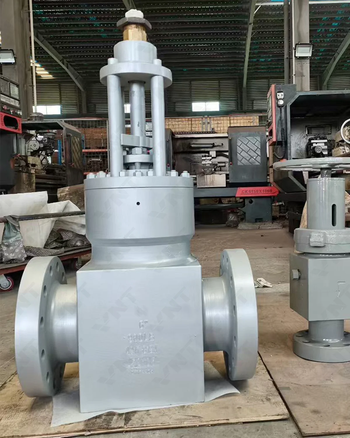
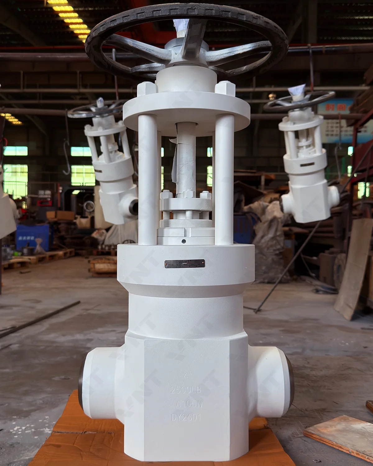
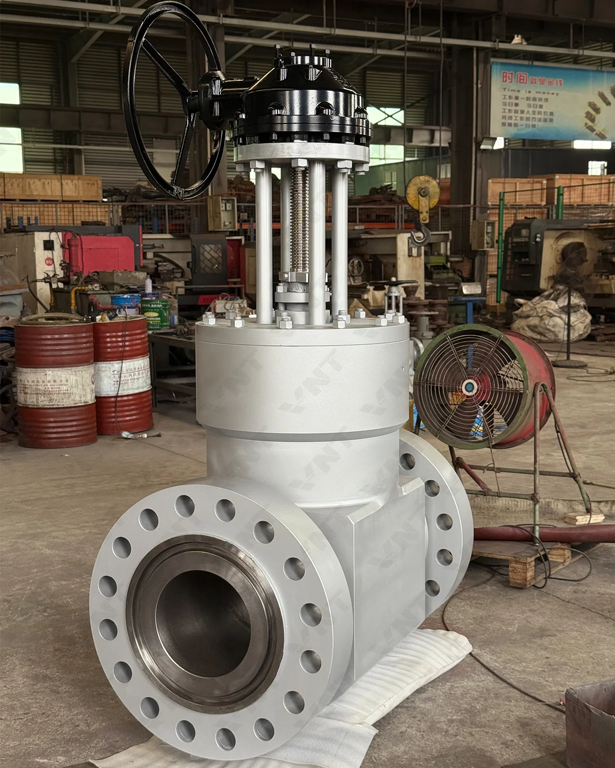
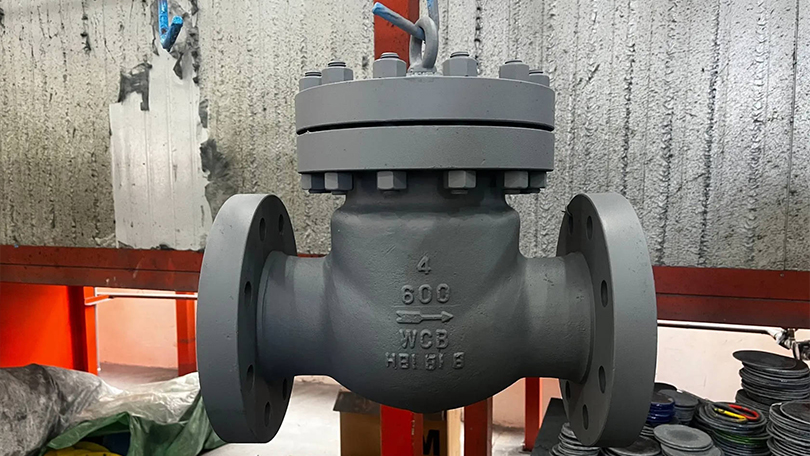
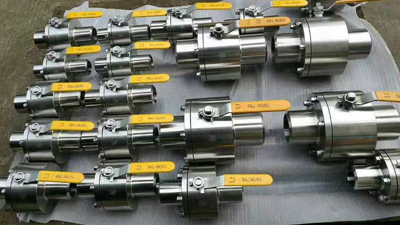
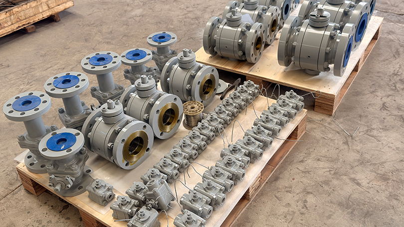
\n\n\n\n Products归档 - Vornet Valve 838209&ev=PageView&noscript=1" />
jessamynlee@vornetvalve.com / jessamyn@vornetvalve.com 📞 +86-17888190118 🌐 EN  |  🇷🇺 RU

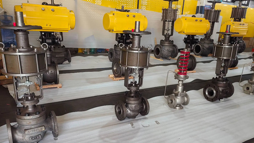
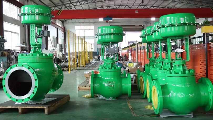
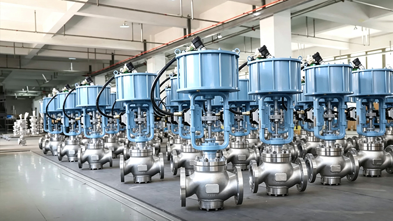
Control Valve Selection Guide: Types, Actuation, Sizing, and How to Choose

📋 Key Takeaways

  • Control valve selection starts with calculating required Cv based on process flow rate, pressure drop, and fluid properties.
  • Globe valves offer precise throttling control while rotary valves provide higher capacity and lower cost per Cv.
  • Actuator type selection considers fail-safe position, response time, and available power sources including pneumatic and electric.
  • Material selection must match fluid corrosivity, temperature range, and erosion potential for reliable long-term service life.
📌 What You’ll Learn: Control valve types (globe, rotary, diaphragm, etc.), actuator selection, sizing fundamentals, flow characteristics, materials, and a practical 8-step selection method.

Control Valve Selection Guide

What Is a Control Valve?

A control valve is a power-operated device that modulates fluid flow in response to a signal from a controller. Specifically, Unlike isolation valves (gate, ball) that only open or close, control valves position the valve trim at any point between fully open and fully closed to maintain process variables — flow rate, pressure, temperature, or level — at set points. This guide covers essential control valve selection information.

Control valves are the final control element in any process control loop. Together with a sensor, transmitter, and controller, they form the closed-loop system that keeps industrial processes running within specification.

Key Components of a Control Valve

  • Body — The pressure-containing housing that connects to the piping
  • Trim — Internal components (seat, disc/plug, stem, cage) that control flow
  • Actuator — Pneumatic, electric, or hydraulic device that positions the trim
  • Positioner — Device that compares the control signal to the valve position and adjusts the actuator accordingly
  • Accessories — I/P converter, limit switches, solenoid valves, air sets, volume boosters

Control Valve Selection Guide

Main Types of Control Valves

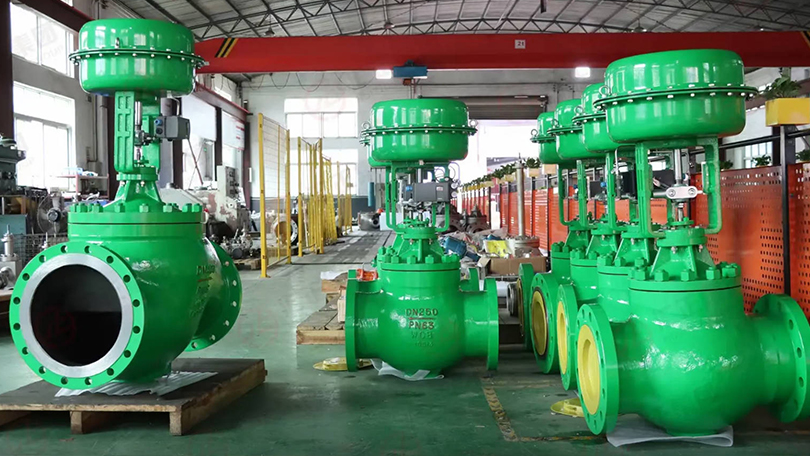
1. Globe Control Valve (Linear Motion)

The most common control valve type. Notably, The plug moves linearly against the seat to modulate flow. Available in single-seat, double-seat, cage-guided, and balanced plug designs.

Best for: Precise throttling, high pressure drop, cavitating or flashing service, wide rangeability.

SubtypeFeatureApplication
Single-seat globeOne seat ring — tight shut-offCritical control, low leakage requirements
Cage-guided globeTrim guided by a cage — stable at high ΔPHigh pressure drop, steam, and erosive service
Balanced plug globePressure-balanced trim — lower actuator forceLarge valves, high pressure, reduced actuator size
Y-pattern globe45° angle body — lower flow resistanceHigh-pressure steam, coking, and high-viscosity fluids

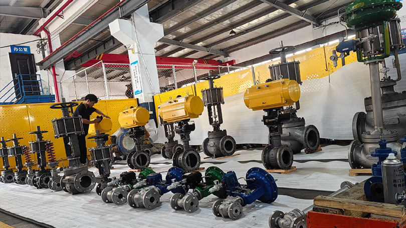
2. Rotary Control Valve (Quarter-Turn)

Rotary control valves use a rotating element (ball, disc, or plug) to modulate flow. For example, They offer higher capacity and lower cost than globe valves for certain applications.

SubtypeFeatureApplication
V-port ball valveV-notch in ball — shearing actionFibrous slurries, pulp & paper, wastewater
Characterized disc (eccentric)Eccentric rotation — low friction, tight sealChemical, pharmaceutical, general service
Eccentric plug valveRotating plug — erosion resistantAbrasive slurries, mining, heavy chemical

3. Diaphragm Control Valve

Uses a flexible diaphragm and weir body design. The diaphragm isolates the fluid from the bonnet and actuator, making it ideal for corrosive, toxic, or sterile fluids.

Best for: Corrosive chemicals, pharmaceutical, food & beverage, water treatment.

4. Control Valve vs. Isolation Valve

FactorControl ValveIsolation Valve (Gate/Ball)
Primary functionModulate / regulate flowOpen / close
PositioningAny point 0-100%Full open or full close
ActuatorPositioner + actuator requiredManual or on/off actuator
Flow characteristicLinear / equal % / quick openingN/A
Shut-off classClass II-VI (control trim)Class 0 (bubble-tight with soft seat)
Cost2-5x higher than equivalent isolation valveLower

Control Valve Selection Guide

Actuator Selection

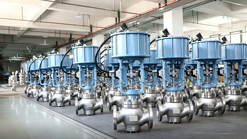
Pneumatic Actuators

Most common in process industries. Fast response, low cost, fail-safe (spring-return). Types: diaphragm (linear), piston (linear/rotary), rack & pinion (quarter-turn).

Electric Actuators

No air supply required. Slower response but precise positioning. Ideal for remote locations, clean environments, and where instrument air is unavailable.

Hydraulic Actuators

Highest thrust capacity. Ultimately, Used for very large valves, high-pressure service, and where rapid response with high force is needed. Common in pipelines and hydroelectric plants.

FeaturePneumaticElectricHydraulic
Response speedFastModerateFastest
Force/thrustModerateHighVery high
Fail-safe optionSpring-return (built-in)Battery backup / capacitorAccumulator
Utility requiredClean, dry instrument airElectric powerHydraulic power unit
Cost$$$$$$
Best forMost process control applicationsRemote/clean areas, precise positioningHigh-force, large-valve, critical service

Control Valve Flow Characteristics

The flow characteristic describes how flow changes relative to valve stem position. This affects loop stability and control range.

  • Linear — Flow is proportional to stem position. Best for level control and constant-pressure systems.
  • Equal Percentage — Equal changes in stem position produce equal percentage changes in flow. Best for pressure control, high ΔP systems, and when most of the system pressure drop is in the piping.
  • Quick Opening — Large flow increase at small openings. Used for on-off service and relief valves.

Control Valve Selection Guide

Control Valve Sizing Fundamentals

Proper sizing prevents cavitation, noise, and premature wear. Key parameters:

  • Cv (Flow Coefficient) — Number of US gallons per minute of 60°F water that flow through the valve with a 1 psi pressure drop
  • Pressure Drop (ΔP) — Difference between upstream and downstream pressure
  • Choked Flow — Maximum flow condition where downstream pressure can no longer increase flow
  • FL (Pressure Recovery Factor) — Accounts for valve geometry’s effect on pressure recovery
  • Rangeability — Ratio of maximum to minimum controllable flow (typically 30:1 to 100:1 for globe valves)

Control Valve Material Selection

ServiceBody MaterialTrim Material
General chemical, water, steamWCB / WCC Carbon Steel304 SS + Stellite seat
Corrosive fluids (acids, caustics)CF8M / CF3M Stainless Steel316L SS, Hastelloy seat
High temperature (425-538°C)WC6 / WC9 Chrome-MolyStellite 6, Inconel
Sour gas (H₂S service)NACE-compliant LCC/SSNACE trim materials
High-pressure steam letdownCage-guided WC9Stellite 6 hardened trim
Sanitary / pharmaceutical316L SS (Ra ≤ 0.8 μm)EPDM / PTFE diaphragm

Control Valve Selection Guide

8-Step Control Valve Selection Method

  1. Define service conditions — Fluid, temperature, pressure, flow rate (normal/max/min), viscosity, specific gravity
  2. Determine valve type — Globe (precise control, high ΔP) or rotary (high capacity, lower cost)
  3. Calculate Cv — Use standard sizing equations per IEC 60534-2-1 or ISA-75.01
  4. Check for cavitation / flashing — Compare ΔP to allowable pressure drop. Use anti-cavitation trim if needed
  5. Select flow characteristic — Linear for level control; equal % for pressure and flow control
  6. Choose body and trim materials — Based on temperature, pressure, corrosion resistance, and erosion
  7. Size the actuator — Account for required thrust, process pressure forces, packing friction, and safety factor
  8. Specify accessories — Positioner, I/P converter, solenoid valve, limit switches, air filter regulator

Common Control Valve Applications by Industry

IndustryApplicationValve Type
Oil RefiningCrude distillation, FCC, hydrotreatingCage-guided globe, angle valves
Chemical & PetrochemicalReactor feed, column control, catalyst additionGlobe, V-port ball, diaphragm
Power GenerationFeedwater regulation, steam attemperation, turbine bypassHigh-pressure globe, angle valves
Oil & Gas ProductionWellhead choke, separator level, pipeline pressureEccentric plug, globe, rotary
PharmaceuticalSterile processing, CIP, WFI systemsDiaphragm, full-bore globe
Water & WastewaterFilter control, chemical dosing, pump recirculationRotary, globe, eccentric plug

Need a Control Valve for Your Process?

Vornet Valve supplies globe control valves, V-port ball valves, and eccentric plug valves with pneumatic, electric, or hydraulic actuation. Sizes NPS 1″ to 36″, Class 150 to 2500. Contact our engineering team for sizing assistance.

Request a Quote →

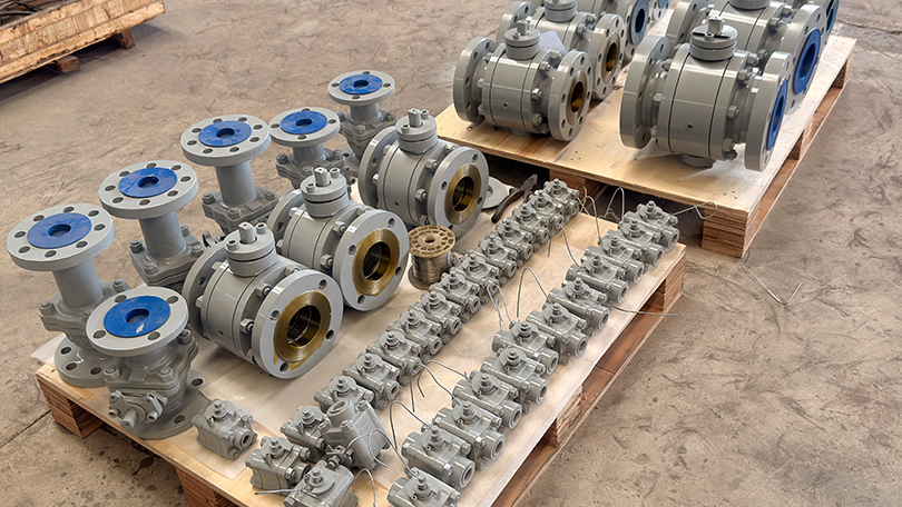
Ball Valve Complete Guide: Types, Selection, Materials, and Applications

📋 Key Takeaways

  • Ball valves use a rotating spherical closure element with a straight-through bore for quarter-turn operation.
  • Floating ball designs suit lower-pressure applications while trunnion-mounted balls handle pressures exceeding 1500 psi.
  • Full-port ball valves minimize pressure drop while reduced-port designs offer cost savings for less demanding services.
  • Seat materials including PTFE, reinforced PTFE, and PEEK determine the valve’s temperature range and sealing performance.
📌 Article Summary

This complete ball valve guide covers everything you need to know: ball valve working principle, main types (floating, trunnion, 3-way, V-port), material selection, pressure ratings, standards, applications, and how to choose the right ball valve for your project. Use the links throughout to dive deeper into specific topics.

Ball Valve

What Is a Ball Valve? — Ball Valve Types

A ball valve is a quarter-turn rotary motion valve that uses a hollow, perforated, and pivoting ball to control flow through it. When the ball’s bore aligns with the pipe axis, flow passes through (open position). When rotated 90 degrees, the solid part of the ball blocks the flow path (closed position). This guide covers essential ball valve types information.

Ball valves are known for their quick shut-off capability, tight sealing, and low operating torque, making them one of the most widely used valve types in industrial fluid control systems.

How Does a Ball Valve Work?

The ball valve operates on a simple principle:

  1. Open position — The ball’s bore is aligned with the flow path, allowing fluid to pass through with minimal pressure drop
  2. Closed position — The ball is rotated 90 degrees, presenting a solid face to the flow path, creating a bubble-tight seal
  3. Partially open — Some ball valve designs (V-port, characterized port) allow throttling control by positioning the ball at intermediate angles

Additionally, Key components include: body, ball, stems (upper and lower), seats (sealing rings), packing, bonnet, and actuator mounting pad.

Ball Valve

Main Types of Ball Valves

1. Floating Ball Valve

In a floating ball valve, the ball is not mechanically fixed in position. It “floats” between two elastomeric or polymeric seat rings. When pressure is applied from the upstream side, the ball is pressed against the downstream seat, creating a seal.

Best for: Smaller sizes (NPS 1/2″ to 8″), lower pressure classes (Class 150-600), general-purpose applications.

Compare floating vs trunnion ball valves in detail →

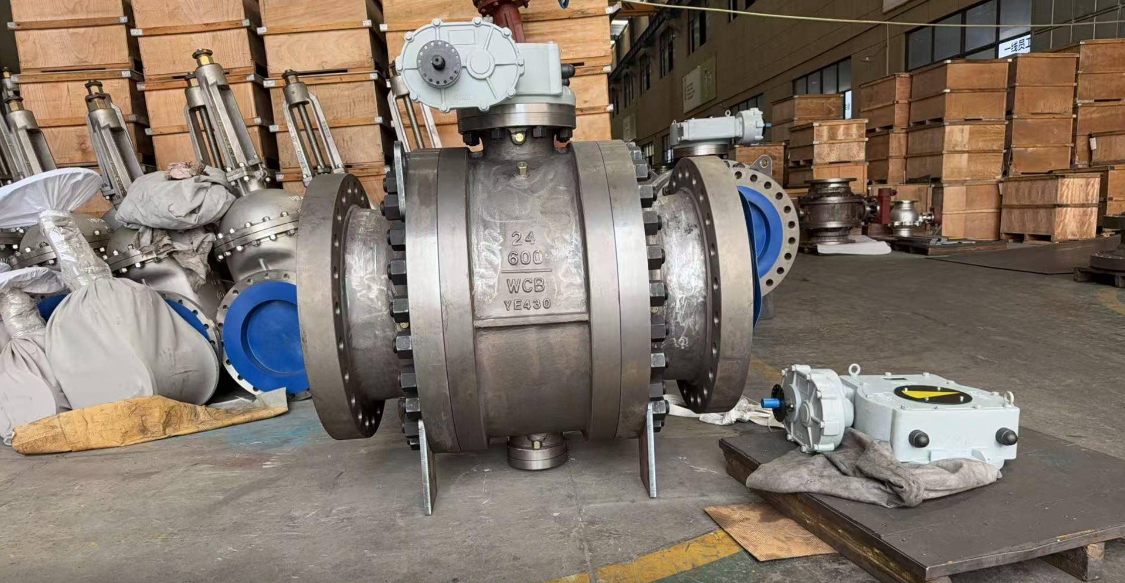
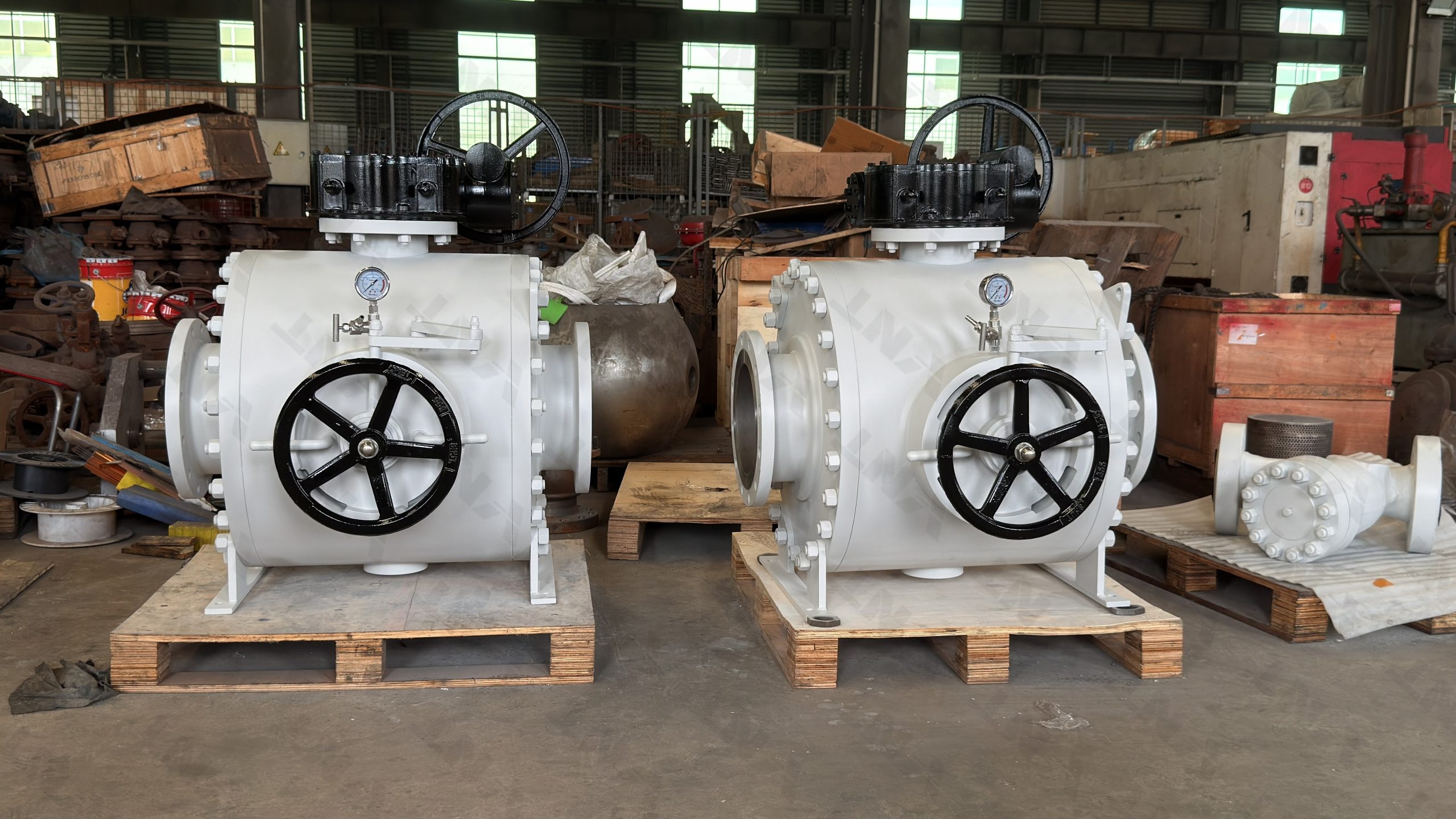
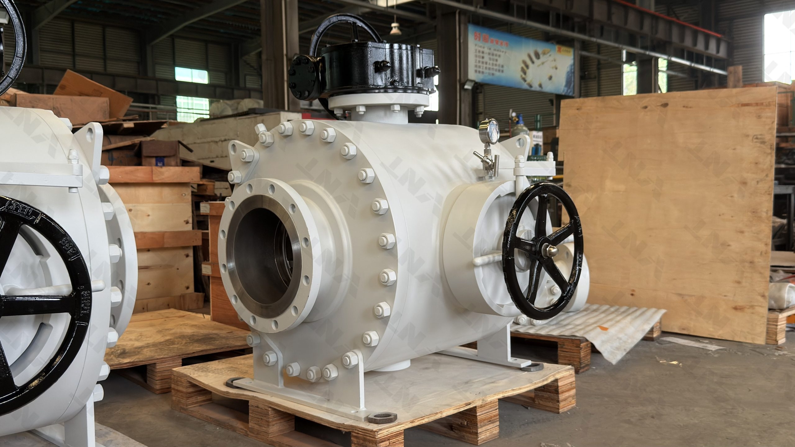
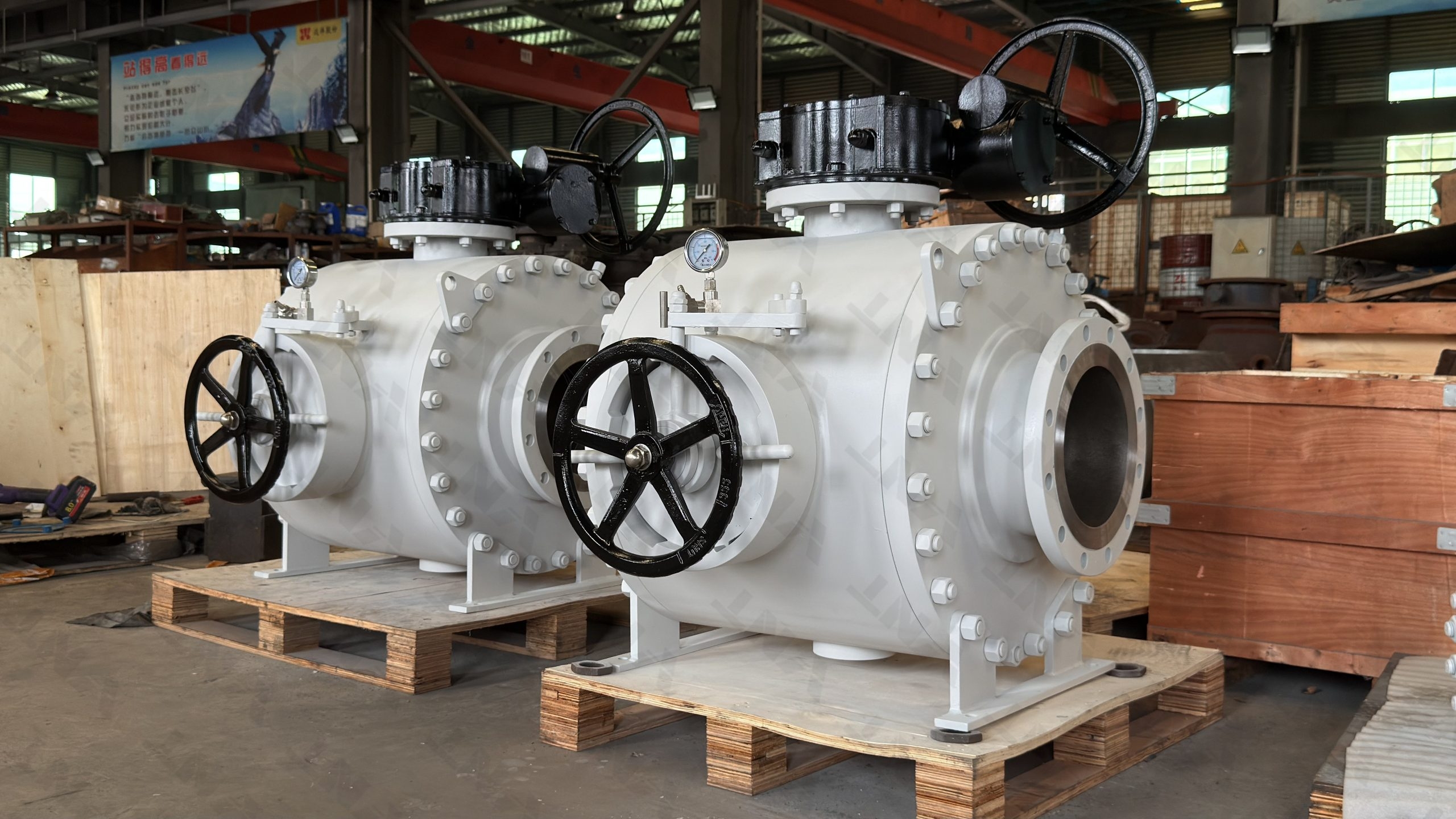
2. Trunnion Ball Valve

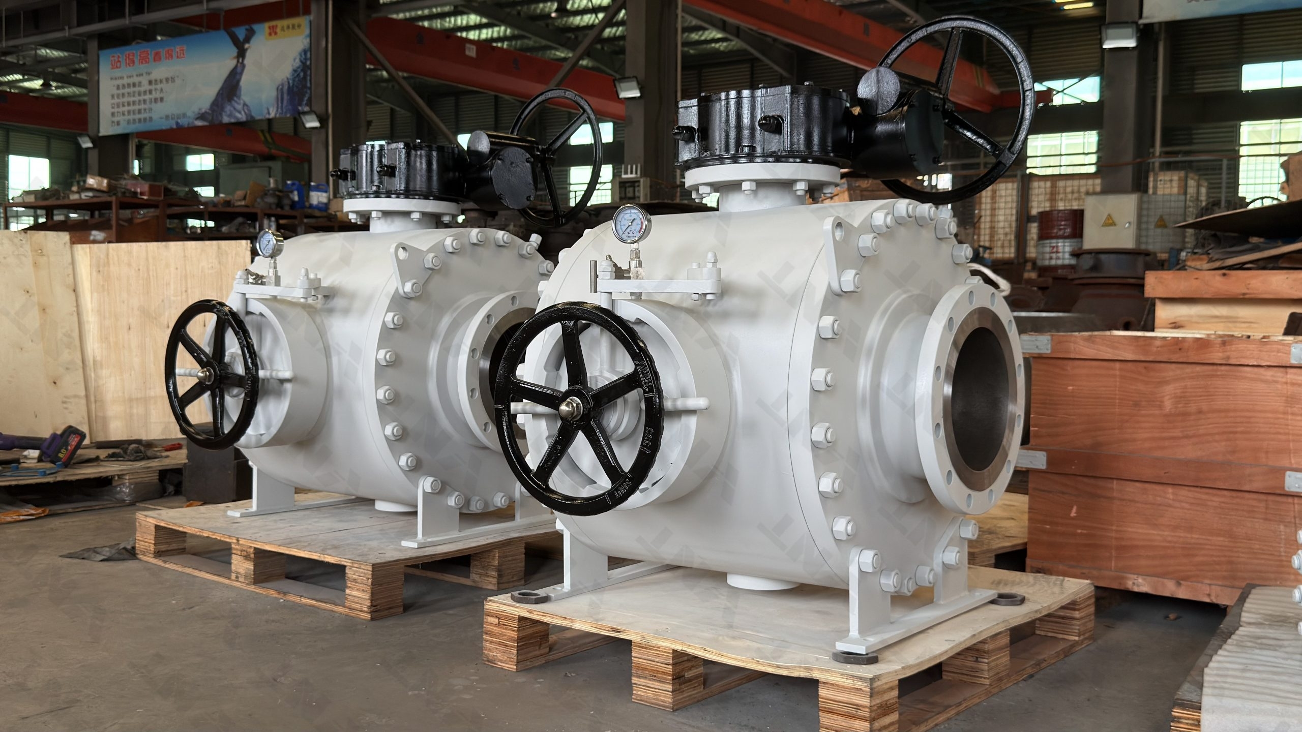
In a trunnion ball valve, the ball is mechanically anchored by a fixed shaft at both the top and bottom (trunnion). Notably, This design absorbs the thrust load generated by line pressure, significantly reducing operating torque and seat wear.

Best for: Large diameters (NPS 4″ to 60″), high-pressure services (Class 600-2500), high-temperature, and critical pipeline isolation applications.

Full trunnion ball valve guide →

3. 3-Way and Multi-Port Ball Valves

Three-way ball valves feature a ball with an L-shaped or T-shaped bore that can direct flow between multiple ports. L-port valves divert flow from one inlet to one of two outlets. T-port valves can mix two inlets into one outlet or split one inlet.

Best for: Flow diversion, mixing, switching between pipelines, and batch processing.

Full 3-way ball valve guide (L-port vs T-port) →

4. Full Bore vs Reduced Bore Ball Valves

FeatureFull Bore (Full Port)Reduced Bore (Venturi)
Bore diameterEqual to pipe IDSmaller than pipe ID (typically 1-2 sizes smaller)
Pressure dropMinimal — same as straight pipeHigher — venturi effect
Pigging capabilityYes — allows pipeline pig passageNo
CostHigher (larger ball, more material)Lower (30-40% savings)
TorqueHigherLower
Best forPigging, high-flow, viscous fluidsGeneral service, cost-sensitive projects

5. V-Port Ball Valve

V-port ball valves have a “V” shaped notch cut into the ball. For example, This design provides improved throttling control and shearing action for fibrous or viscous fluids. The flow characteristic is approximately equal percentage, offering good control rangeability.

Best for: Throttling/control applications, pulp and paper, wastewater treatment, viscous fluids.

6. High Temperature Ball Valve

High-temperature ball valves use special material combinations (Inconel 718/625 bodies, Stellite hardfacing, metal seats) to operate reliably at temperatures from 250°C up to 1000°C. These are critical for petrochemical, power generation, and metallurgical applications.

High temperature ball valve material guide →

Ball Valve

Ball Valve Material Selection

Body Materials

MaterialStandardTemperature RangeApplication
WCB Carbon SteelASTM A216-29°C to 425°CGeneral service, oil & gas, water
CF8M / CF3M Stainless SteelASTM A351-196°C to 538°CCorrosive media, food, chemical
F304 / F316 Forged SSASTM A182-196°C to 538°CHigh-pressure, small-bore valves
Duplex / Super Duplex SSASTM A890 / A995-50°C to 315°CSour gas, seawater, chloride-rich
Inconel 625 / 718ASTM B564-196°C to 980°CHigh-temperature, extreme corrosion
TitaniumASTM B367 / B381-196°C to 315°CHighly corrosive chemical media
Monel 400ASTM B564-196°C to 538°CHydrofluoric acid, marine
Alloy 20ASTM B473-196°C to 538°CSulfuric acid, chemical processing

Seat and Seal Materials

Seat MaterialMax TemperatureKey Feature
PTFE / RPTFE200°CLow friction, chemical resistant, bubble-tight
Reinforced PTFE (25% Glass/Carbon)232°CHigher mechanical strength, reduced cold flow
PEEK260°CExcellent wear resistance, high strength
Nylon150°CGood wear, lower cost
Devolite (PPL)260°CGood chemical resistance, high temp
Metal-seated (Stellite/SS)538-980°CHigh temperature, abrasive media, fire-safe

Ball Valve Standards and Specifications

StandardScope
API 6DPipeline ball valves — design, manufacturing, and testing for transmission pipelines
ASME B16.34Pressure-temperature ratings, dimensions, and tolerances
ASME B16.5 / B16.47Flange dimensions and drilling templates
API 598Valve inspection and pressure testing
ISO 17292Metal ball valves for petroleum, petrochemical, and allied industries
ISO 5211Actuator mounting flange dimensions
API 607 / ISO 10497Fire-safe testing
NACE MR0175 / ISO 15156Sour service (H₂S) material requirements

Ball Valve

How to Select the Right Ball Valve

  1. Define operating conditions: Medium (liquid/gas/steam), pressure class, temperature, flow rate
  2. Choose the valve type: Floating (small, low pressure), trunnion (large, high pressure), 3-way (mixing/diversion), V-port (throttling)
  3. Select body material: Based on corrosion resistance, temperature range, and cost
  4. Choose seat material: Based on temperature, sealing requirements, and media compatibility
  5. Determine end connections: Flanged (ANSI/ASME/DIN), threaded, socket weld, butt weld
  6. Select bore size: Full bore (low pressure drop, pigging) or reduced bore (cost saving)
  7. Choose actuation: Manual (handle/gear), pneumatic, electric, or hydraulic
  8. Check compliance: Ensure the valve meets applicable API/ASME/ISO standards

Common Ball Valve Applications by Industry

IndustryApplicationPreferred Ball Valve Type
Oil & Gas (Upstream)Wellhead, flowlines, gatheringTrunnion-mounted, API 6D
Oil & Gas (Pipeline)Transmission, pig launching, isolationFull-bore trunnion, fire-safe
Chemical ProcessingReactor feed, corrosive media handlingChemically-compatible seat, SS/Alloy body
Power GenerationBoiler isolation, steam, cooling waterHigh-temp metal seat, trunnion
Water & WastewaterDistribution, treatment, filtrationFloating, full-bore, epoxy-coated
PharmaceuticalClean-in-place, hygienic processingFull-bore, SS body, clamp ends
HVACChilled water, hot water, cooling towersFloating, 2-way or 3-way
MarineBallast, seawater cooling, fuel transferDuplex SS, trunnion

Ball Valve Advantages and Limitations

Advantages

  • Quick 90-degree quarter-turn operation (open to close)
  • Bubble-tight shut-off with soft seats
  • Low operating torque compared to gate and globe valves
  • Compact design — shorter face-to-face dimensions than gate valves
  • Bi-directional sealing capability
  • Suitable for automated actuation
  • Low pressure drop in full-open position

Limitations

  • Not ideal for throttling (unless V-port or characterized design)
  • Soft seats limit maximum temperature (PTFE ≈ 200°C; metal seats needed for high temp)
  • Can trap cavity pressure with certain media
  • More expensive than gate valves for very large diameters (NPS 24+)

Ball Valve vs Other Valve Types

FactorBall ValveGate ValveGlobe ValveButterfly Valve
Operation90° quarter-turnMulti-turn linearMulti-turn linear90° quarter-turn
Shut-off✅ Bubble-tight✅ Tight (metal)✅ Excellent⚠️ Good (soft seat)
Throttling❌ Poor (V-port: ⚠️ Fair)❌ Poor✅ Excellent⚠️ Fair
Pressure dropVery lowLowModerate-HighLow-Moderate
SpeedFastSlowSlowFast
Size rangeNPS 1/2″ to 60″NPS 1/2″ to 60″NPS 1/2″ to 48″NPS 2″ to 120″
Cost (NPS 6″, Class 150)$$$$$$

Ball Valve Maintenance Tips

  • Periodically cycle the valve (open-close) to prevent seat sticking
  • Check stem packing for leakage — tighten or replace as needed
  • Lubricate stem and gearbox per manufacturer schedule
  • For high-temperature service, ensure proper thermal cycling procedures
  • Replace seat seals every 3-5 years for standard service; more frequently for severe service
  • Store spare valve with ball in partially open position (5-10°) to prevent seat deformation

Ball Valve

Ball Valve FAQ

Q1: What is the difference between floating and trunnion ball valves?

A floating ball valve has a ball that rests between two seat rings and relies on line pressure to create a seal against the downstream seat. Ultimately, In a trunnion ball valve, the ball is anchored by fixed shafts at top and bottom, absorbing pressure thrust and reducing seat wear. Floating valves suit smaller sizes (NPS 1/2″ to 8″) and lower pressures (Class 150-600). Trunnion valves handle large diameters (NPS 4″ to 60″), high pressures (Class 600-2500), and critical pipeline services. See our trunnion vs floating ball valve guide.

Q2: What is the maximum operating temperature for a ball valve?

For soft-seated ball valves: PTFE/RPTFE seats max 200°C, PEEK seats max 260°C, Devolite/PPL seats max 260°C. For high-temperature service, metal-seated ball valves with Stellite hardfacing operate up to 538°C, and special Inconel body designs with Stellite trim can handle up to 980°C. See our high temperature ball valve guide for details.

Q: Are ball valves suitable for throttling and flow control?

Standard ball valves are designed for on/off isolation. However, V-port ball valves with a V-shaped notch provide an approximately equal-percentage flow characteristic suitable for throttling. For precise control, globe valves or control valves are typically preferred. See our control valve selection guide for a comparison of valve types for throttling service.

Q: When should I choose full bore vs reduced bore ball valves?

Choose full bore for: minimal pressure drop, pipeline pigging, viscous/slurry fluids, and maximum flow. Choose reduced bore for: general service where 30-40% cost savings matter, no pigging requirement, and acceptable higher pressure drop. Full bore is standard in pipeline transmission; reduced bore is common in general industrial applications.

Q: What standards apply to ball valve design and testing?

Key standards include: API 6D (pipeline design and testing), ASME B16.34 (pressure-temperature ratings), API 598 (inspection and testing), ISO 17292 (metal ball valves), API 607 (fire-safe testing), and NACE MR0175 (sour service). All Vornet ball valves are manufactured to these applicable API, ASME, ASTM, and EN standards.

Need a Ball Valve for Your Project?

Vornet Valve supplies floating, trunnion, and 3-way ball valves in sizes NPS 1/2″ to 60″, Class 150 to 2500, in carbon steel, stainless steel, duplex, and exotic alloys. API 6D certified and fire-safe rated.

Get a Quote →

📖 Related Guides:
Trunnion vs Floating Ball Valve: Complete Comparison
3-Way Ball Valve L-Port vs T-Port Guide
High Temperature Ball Valve Material Guide (250°C-1000°C)
Industrial Valve Materials & Trim Equivalents Guide

🏭 Looking for a Reliable Ball Valve Manufacturer?

Vornet Valve is a China-based industrial valve manufacturer with over 20 years of experience. We manufacture ball valves to API 6D, ASME B16.34, API 608, and ISO 17292 standards — including floating, trunnion-mounted, 3-way, V-port, and high-temperature ball valves. Available in sizes NPS 1/2″ to 60″, Class 150 to Class 2500, with materials from WCB carbon steel to duplex stainless steel and Hastelloy. Our ball valves are used in oil & gas, LNG, chemical processing, power generation, and marine applications worldwide.

Contact us today for a quote or technical consultation:

What Is a Control Valve? Complete Guide to Types, Features, and Applications

📋 Key Takeaways

  • Control valves modulate fluid flow using an actuator-driven closure element positioned by a controller signal.
  • Major control valve types include globe, ball, butterfly, plug, diaphragm, and pinch valves, each with distinct flow characteristics.
  • Globe valves offer linear flow characteristics ideal for throttling; ball and butterfly valves suit on-off and modulating services.
  • Proper actuator sizing, positioner calibration, and flow coefficient (Cv) selection are essential for accurate loop control.
📌 What You’ll Learn:

Control valve types — globe, rotary ball, butterfly, cage-guided, and diaphragm — how actuators and positioners work, flow characteristics (linear, equal percentage, quick opening), critical selection criteria including Cv, pressure drop, and noise control, plus a complete Class 300 selection guide with actuator sizing tables. This guide covers everything from basic control valve principles to advanced applications across oil and gas, power generation, chemical, water, pharmaceutical, and food industries.

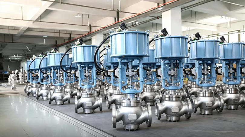
This control valve selection guide covers types, sizing, actuators, positioners, and applications for industrial process control. A control valve is a power-operated device used to regulate the flow rate, pressure, temperature, or level of a process fluid by varying the size of the flow passage as directed by a control system signal. Unlike manual valves that require a human operator to turn a handwheel, a control valve receives an electronic or pneumatic signal from a process controller and automatically positions its internal throttling element — such as a plug, ball, or disc — to maintain the desired process variable at its setpoint.

Control valves are the final control element in nearly every industrial process loop. They work in conjunction with sensors (transmitters) that measure the process variable and controllers (PLCs, DCS, or standalone PID controllers) that compare the measured value to the setpoint and generate an output signal. The control valve receives this signal through its actuator and positioner, adjusts its opening position accordingly, and thereby influences the process condition to match the setpoint. This closed-loop control architecture forms the foundation of modern industrial automation.

The global control valve market was valued at approximately USD 8.5 billion in 2025 and is projected to exceed USD 12 billion by 2032, driven by increasing automation in oil and gas, power generation, chemical processing, water treatment, and pharmaceutical manufacturing. Ultimately, Control valves are manufactured in sizes from NPS 1/2″ to 48″ and pressure classes from Class 150 to Class 4500, in materials ranging from cast carbon steel to exotic alloys such as Hastelloy, Monel, and Inconel. Design, testing, and performance criteria are governed by international standards including IEC 60534, ISA 75.01, ASME B16.34, and API 598.
Control Valve

How Does a Control Valve Work? — Control Valve Types

A control valve operates through the coordinated action of three primary subsystems: the valve body (which contains the flow-controlling element), the actuator (which provides the motive force to position the element), and the positioner (which precisely controls the actuator’s position in response to the control signal).

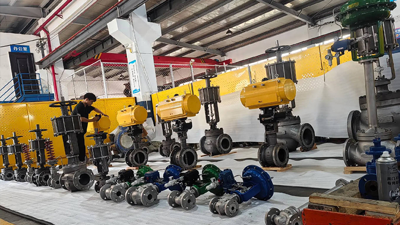
The operating sequence is as follows: A process transmitter measures the actual process variable (flow rate, pressure, temperature, or level) and sends a 4-20 mA signal to the controller. The controller compares this value to the desired setpoint and calculates an error. Based on the error, the controller generates a control output signal (typically 4-20 mA or 3-15 PSI pneumatic). The control valve’s positioner receives this signal, compares it to the actual valve stem position (feedback by a mechanical linkage or magnetic sensor), and adjusts the pneumatic or electric power delivered to the actuator. The actuator moves the valve stem to a new position, changing the flow area through the valve until the process variable reaches the setpoint.

The total response time — from the moment the controller detects a process deviation to the moment the valve stem reaches its new position — is typically 1 to 10 seconds depending on valve size, actuator type, and process dynamics. This closed-loop correction cycle repeats continuously, often several times per second, to maintain stable process conditions.
Control Valve

Key Components of a Control Valve Assembly

A complete control valve assembly consists of several components that work together to provide accurate, reliable flow control. Understanding each component is essential for proper selection, installation, and maintenance.

Valve Body

The valve body houses the internal trim (seat, disc/plug, cage, stem) and contains the process fluid under pressure. It provides the flow path and connection to the piping system. Body materials are selected based on pressure class, temperature, and fluid corrosivity — ranging from WCB carbon steel for general service to CF8M stainless steel, WC6/WC9 alloy steel, and Hastelloy for severe service. End connections include flanged (raised face, RTJ), threaded, butt-weld, socket-weld, and clamp-type (sanitary).

Actuator

The actuator provides the mechanical force required to position the valve’s throttling element. Actuators are classified by their power source: pneumatic (spring-diaphragm or piston), electric, electro-hydraulic, or manual (handwheel for backup). The actuator must generate sufficient thrust to overcome the unbalanced forces from process pressure, packing friction, and flow-induced forces at all valve positions. Actuator sizing is one of the most critical steps in control valve selection.

Positioner

The positioner is a precision control device mounted on the actuator that receives the control signal (4-20 mA, 3-15 PSI, or digital fieldbus) and adjusts the actuator’s position accordingly. It compares the input signal to the actual valve stem position (feedback signal) and modulates the actuator supply pressure or power until the positions match. Modern digital positioners (also called smart positioners) offer advanced features including HART or Foundation Fieldbus communication, auto-calibration, diagnostic monitoring, valve signature analysis, and predictive maintenance alerts.

I/P Transducer

The current-to-pressure (I/P) transducer converts a 4-20 mA electronic control signal into a proportional 3-15 PSI pneumatic signal for the positioner or actuator. In smart digital positioners, the I/P function is integrated within the positioner electronics. For analog systems, a stand-alone I/P transducer is used. Accuracy, air consumption, vibration resistance, and response time are key selection criteria for I/P transducers.

Accessories

Common control valve accessories include: air filter regulators (to provide clean, regulated supply air), solenoid valves (for on-off shutoff or emergency shutdown), volume boosters (to increase actuator speed), limit switches (for remote position indication), and locking devices or handwheels (for manual backup operation during instrument air failure).
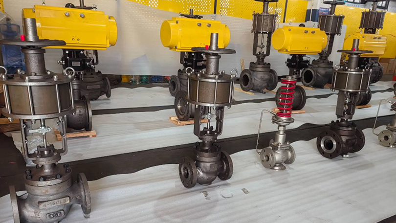
Control Valve

Control Valve Selection Guide: Types of Control Valves

Control valves are classified by the motion of the internal throttling element (linear vs. rotary stroke) and by the internal trim design. Each type has distinct advantages for specific applications, pressure ranges, and fluid characteristics.

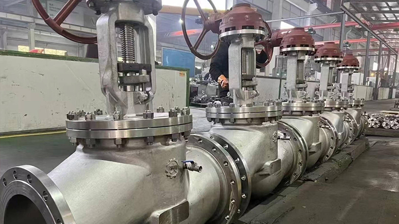
1. Globe-Style Control Valve

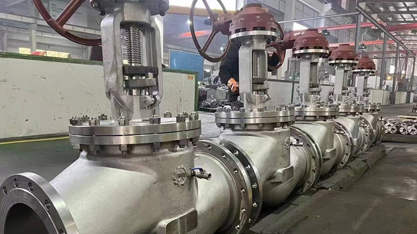
The globe-style control valve uses a linear-motion plug that moves perpendicular to the seat ring to regulate flow. Specifically, It is the most widely used control valve type in the process industry, offering excellent throttling accuracy, a wide range of Cv values, and compatibility with high-pressure and high-temperature services. The flow path through a globe control valve changes direction, creating a predictable pressure drop that enables stable control even under varying process conditions. Globe-style control valves are available in single-port (for standard throttling) and double-port (for reduced actuator force requirements in high-pressure applications) configurations. Cage-guided globe valves (described below) are the most common variant.

2. Rotary Control Valve (Ball Valve)

Rotary control ball valves use a quarter-turn (90-degree) rotating ball with a cylindrical or segmented bore to regulate flow. The ball rotates from fully open (bore aligned with flow path) to fully closed (solid face blocking flow). Segmented ball valves (also called V-notch or V-port ball valves) use a V-shaped notch in the ball that provides an equal-percentage flow characteristic ideal for control applications. Rotary control ball valves offer high flow capacity (Cv), tight shutoff, low cost relative to globe valves of the same size, and resistance to clogging in dirty or viscous services. They are widely used in pulp and paper, mining, oil and gas, and water treatment applications.

3. Rotary Control Valve (Butterfly Valve)

Butterfly control valves use a rotating disc that pivots in the center of the pipe to regulate flow. High-performance butterfly valves with eccentric disc designs (double-offset and triple-offset) provide excellent throttling characteristics, bubble-tight shutoff, and long service life. Butterfly control valves are the most economical choice for large pipe sizes (NPS 6″ and above) and are widely used in water distribution, HVAC, power plant cooling water, and low-pressure gas applications. Their compact face-to-face dimensions and lightweight construction reduce installation cost and piping support requirements.

4. Cage-Guided Control Valve

Cage-guided control valves are a specialized type of globe-style valve where the plug moves within a cylindrical cage that serves both as a flow-directing element and as a plug alignment guide. The cage contains precisely machined openings (ports) that determine the flow characteristic — linear, equal percentage, or quick opening — without changing the plug or seat. Cage guidance provides superior vibration dampening, reduced noise generation, and protection against side-loading of the stem. Cage-guided valves are the preferred choice for high-pressure drop applications, services with high fluid velocities, and applications requiring anti-cavitation or low-noise trim. The cage also facilitates easy trim replacement without removing the valve body from the pipeline.

5. Diaphragm Valve

Diaphragm valves use a flexible membrane (diaphragm) clamped between the valve body and bonnet. When the actuator pushes a compressor down onto the diaphragm, it seals against a weir in the body, throttling flow. When lifted, flow passes freely over the weir. Diaphragm valves are ideal for sanitary, pharmaceutical, food, and bioprocessing applications because the weir-body design eliminates crevices and dead spaces where bacteria could grow. The diaphragm completely isolates the bonnet and actuator from the process fluid, making these valves suitable for corrosive or sterile media. Materials include PTFE, EPDM, and silicone diaphragms with body materials of 316L stainless steel, PVC, CPVC, and polypropylene.
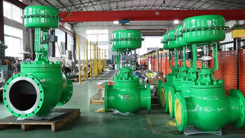
Control Valve

Control Valve Flow Characteristics

The relationship between the valve’s opening (stem travel) and the resulting flow rate (Cv) is called the flow characteristic. For example, Selecting the correct characteristic is critical for stable process control. The three standard characteristics per IEC 60534 are described below.

Linear Characteristic

In a linear characteristic valve, the flow capacity (Cv) increases proportionally with stem travel. A 50% stem position produces approximately 50% of the full-open Cv. Linear characteristics are best suited for processes where the pressure drop across the valve remains relatively constant regardless of flow rate — such as level control in tanks, flow control with constant differential pressure, and certain temperature control applications. Linear valves provide consistent gain (change in flow per change in signal) across the entire operating range.

Equal Percentage Characteristic

Equal percentage (EQ%) is the most common characteristic for throttling control. In an equal percentage valve, equal increments of stem travel produce equal percentage changes in the existing flow coefficient. For example, moving from 50% to 60% travel might increase Cv by 25% of the current value, while moving from 60% to 70% travel also increases Cv by 25% of the new value. This characteristic compensates for the decreasing pressure drop across the valve as flow increases in a typical system. Equal percentage valves provide stable control across a wide range of process conditions and are the default choice for pressure control, temperature control, and flow control in systems with varying differential pressure.

Quick Opening Characteristic

Quick opening valves provide maximum flow increase at the beginning of stem travel. A small initial stem movement (10-20% travel) produces a large change in Cv (typically 70-80% of full Cv). Quick opening characteristics are used primarily for on-off and emergency shutdown applications where rapid flow initiation is required. They are also used in relief valve and dump valve applications. Quick opening is not recommended for precise throttling control because the gain is very high at low openings and very low at high openings, making stable control difficult.

Actuator Types for Control Valves

The actuator is the power source that positions the control valve’s internal element. The choice of actuator type depends on the available utility supply, required thrust, stroking speed, fail-safe requirements, and environmental conditions.

Pneumatic Spring-Diaphragm Actuator

The spring-diaphragm actuator is the most common actuator type in the process industry. It consists of a flexible diaphragm connected to the valve stem through a spring-loaded plate. Pneumatic pressure applied to the diaphragm chamber compresses the spring and moves the stem. Loss of supply air causes the spring to return the stem to its fail-safe position (fail-open or fail-closed depending on spring orientation). Advantages include simple construction, low cost, reliable fail-safe operation, and a long service life. Limitations include limited thrust capability (typically suitable up to Class 600 for smaller valves) and susceptibility to supply pressure variations.

Pneumatic Piston Actuator

Piston actuators use a piston in a cylinder instead of a diaphragm, supplied with pneumatic pressure. They generate significantly higher thrust than spring-diaphragm actuators of the same size and can operate at higher supply pressures (up to 150 PSI or more). Piston actuators are used for high-pressure control valves (Class 900 and above), large valve sizes, and applications requiring fast stroking speeds. Fail-safe operation requires an external spring module or a hydraulic/pneumatic fail-safe system since piston actuators do not have a built-in fail-safe spring as diaphragm actuators do.

Electric Actuator

Electric actuators use an electric motor (AC or DC) coupled to a gear train and a stem nut to convert rotary motion into linear or quarter-turn motion. They are self-contained units requiring only electrical power — no instrument air is needed. Modern electric actuators offer precise position control with resolution down to 0.1%, integrated positioners with fieldbus communication (Profibus, Modbus, Foundation Fieldbus), and fail-safe options using springs or batteries. Electric actuators are preferred in remote locations without instrument air supply, in clean rooms (no exhaust air), and in applications requiring data logging and sophisticated diagnostics. Their primary disadvantage is higher initial cost compared to pneumatic actuators.

Hydraulic Actuator

Hydraulic actuators use pressurized hydraulic fluid to generate very high thrust forces in a compact package. They are used for the most demanding control valve applications — very high pressure (Class 2500+), very large valve sizes (NPS 24″ and above), and applications requiring extremely fast stroking speeds or precise positioning under high unbalanced loads. Hydraulic actuators can maintain position without continuous power consumption using lock valves. They require a hydraulic power unit (pump, reservoir, accumulator) and are typically specified for specialized applications such as turbine control, high-pressure let-down stations, and subsea production systems.

Critical Selection Criteria for Control Valves

Proper control valve selection requires a thorough analysis of process conditions, fluid properties, and performance requirements. The following criteria are essential for correct sizing and selection.

Flow Coefficient (Cv)

The flow coefficient Cv is the number of US gallons per minute of water at 60°F that will flow through the valve with a 1 PSI pressure drop. Cv is the fundamental sizing parameter for control valves and is calculated using the standard ISA-75.01 sizing equations. The required Cv depends on the maximum and normal flow rates, inlet pressure, allowable pressure drop, specific gravity, temperature, and whether the flow is laminar, turbulent, or choked. Undersizing leads to insufficient flow capacity and excessive pressure drop; oversizing causes poor control at low flow rates (the valve operates near its closed position where gain is high and control is unstable). The general rule is to select a valve such that the normal operating position is between 50% and 80% open.

Pressure Drop and Choked Flow

The pressure drop across a control valve affects both the flow rate and the potential for cavitation or flashing. As flow velocity increases through the valve restriction, the static pressure drops. If the pressure at the vena contracta (the minimum cross-section area inside the valve) falls below the fluid’s vapor pressure, vapor bubbles form (flashing). If the bubbles subsequently collapse as pressure recovers downstream, cavitation occurs. Cavitation can cause severe physical damage to valve trim, noise, and vibration. The pressure recovery factor (FL) quantifies a valve’s tendency to cavitate — lower FL values indicate higher pressure recovery and greater cavitation risk. Anti-cavitation trim designs use multiple stages of pressure reduction to keep the pressure above vapor pressure throughout the valve.

Noise Prediction and Control

Control valves are a major source of noise in industrial plants, generated by turbulent flow, mechanical vibration, and cavitation. Valve noise is predicted using the IEC 60534-8-3 standard for aerodynamic noise and IEC 60534-8-4 for hydrodynamic noise. Excessive noise indicates high fluid energy dissipation that can damage trim components and cause piping vibration. Low-noise trim designs — including multi-stage pressure reduction, tortuous-path cages, and diffuser plates — reduce noise by 10-20 dBA compared to standard trim. For applications where noise must be controlled for occupational or environmental compliance, low-noise control valves, inline silencers, and acoustic insulation are available.

Rangeability and Turndown

Rangeability is the ratio of maximum controllable Cv to minimum controllable Cv. Turndown is the ratio of maximum to minimum flow rate the valve can control within acceptable accuracy. A valve with good rangeability (50:1 or higher) can handle both high-flow and low-flow conditions without requiring a second parallel control valve. Globe-style control valves typically offer rangeability of 30:1 to 50:1, while segmented ball valves can achieve 100:1 or higher. Rangeability requirements should be matched to process flow variations: batch processes with wide flow swings need high rangeability, while continuous processes with stable flow rates need moderate rangeability.

Control Valve vs. On-Off Valve: Key Differences

Control valves and on-off (isolation) valves serve fundamentally different purposes in a piping system. Understanding when to use each type is critical for proper system design and reliable operation.

CharacteristicControl ValveOn-Off Valve
Primary FunctionRegulate flow at any position between open and closedIsolation — fully open or fully closed only
PositioningModulated to any intermediate position (e.g., 45% open)Binary — either fully open (100%) or fully closed (0%)
ActuatorPositioner-controlled actuator with precise stem positioningSimple open/close actuator (spring-return or double-acting)
Throttling PrecisionExcellent — position accuracy within 0.5-1.0% of spanNone — not designed for intermediate positioning
Trim DesignSpecially profiled plug/cage for specific flow characteristicStandard gate, ball, or disc for maximum flow area
Cv vs. Pipe SizeLower Cv for same pipe size — designed for pressure dropHigher Cv — minimal pressure drop when fully open
Control SignalReceives 4-20 mA, 3-15 PSI, or fieldbus control signalReceives discrete on/off signal (24 VDC, 120 VAC, or pilot air)
Fail-Safe PositionMaintain last position, or move to fail-open/fail-closed on signal lossSpring-return to fail-open or fail-closed on power/air loss
Cycle LifeDesigned for frequent cycling (thousands to millions of cycles)Designed for infrequent operation (tens to hundreds of cycles per year)
CostHigher — positioner, smart electronics, precision trim add costLower — simpler actuator, no positioner, standard trim
Typical ServiceProcess control, flow regulation, pressure/temperature controlIsolation, block valve, emergency shutdown, on/off service

A critical design rule: never use an on-off valve for throttling service. Partial opening of a gate valve or ball valve designed for on-off service causes high-velocity flow across the seat, wire drawing, seat erosion, and premature failure. Conversely, a control valve may be used for isolation if it provides tight shutoff, but it is not the most economical choice when only isolation is required.

Applications by Industry

Control valves are used across nearly every industrial sector that requires automated process control. The following describes key applications by industry.

Oil and Gas. In upstream oil and gas, control valves regulate wellhead flow, gas lift injection rates, separator level control, and pipeline pressure. In midstream, they provide custody transfer flow control at metering stations, pipeline pressure regulation, and compressor station antisurge control. In downstream refineries, control valves are used in crude distillation, catalytic cracking, hydroprocessing, sulfur recovery, and product blending. Materials range from carbon steel for sweet service to stainless steel and Incoloy for sour gas (NACE MR0175 compliant) and high-temperature services. Pressure classes from Class 150 to Class 2500.

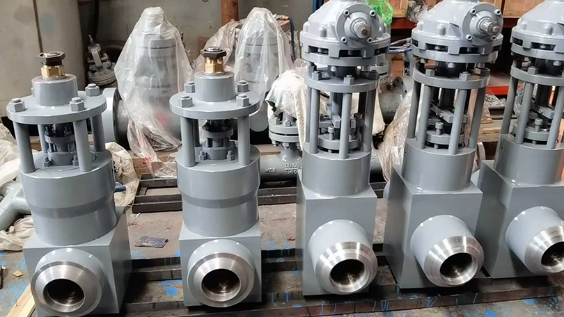
Power Generation. Power plants use control valves extensively for boiler feedwater regulation, steam temperature control (attemperation), turbine bypass control, condensate recirculation control, and cooling water systems. Additionally, High-pressure Y-type globe control valves with anti-cavitation trim are standard for supercritical and ultra-supercritical boiler applications. Quick-opening control valves are used for turbine bypass and safety-related services.

Chemical and Petrochemical. Chemical processing requires precise control of reactants, catalysts, and product flows. Notably, Control valves handle corrosive chemicals (acids, caustics, chlorides), high-temperature processes, and hazardous fluids. Sanitary diaphragm control valves are used in specialty chemical and pharmaceutical intermediate production. Materials include 316L stainless steel, Hastelloy C276, Monel 400, titanium, and PTFE-lined bodies.

Water and Wastewater. Municipal water treatment facilities use control valves for chemical dosing (chlorine, fluoride, coagulants, polymers), filter effluent flow control, filter backwash sequencing, and distribution system pressure regulation. Large butterfly control valves (NPS 24″ to 72″) are common in raw water intake and transmission mains. Globe control valves handle chemical injection with high turndown requirements.

Pharmaceutical and Biotechnology. In pharmaceutical manufacturing, control valves must meet FDA, cGMP, and USP Class VI requirements for clean-in-place (CIP) and sterilize-in-place (SIP) operations. Weir-type diaphragm control valves with 316L SS bodies, electropolished internal surfaces, and sanitary clamp connections are standard. Applications include WFI (water for injection) distribution, bioreactor temperature control, buffer preparation, and clean steam regulation.

HVAC and Building Management. Commercial building HVAC systems use control valves for hot water, chilled water, and condenser water regulation in heating and cooling coils, radiators, heat exchangers, and cooling towers. Characterized control ball valves and globe-style control valves with 0-10 VDC or 4-20 mA control signals are typical. Applications include VAV box reheat control, chiller plant optimization, and district heating/cooling networks.

Food and Beverage. Food and beverage processing uses CIP-compatible control valves for ingredient dosing, heat exchanger temperature control, carbonation, and packaging line flow regulation. Materials include 304L and 316L stainless steel with EPDM, silicone, or PTFE seals. Diaphragm control valves are preferred for viscous fluids, particulate-containing products, and applications requiring full drainability.

Control Valve Class 300 Selection Guide

The following selection guide provides a practical reference for specifying control valves in Class 300 applications, which are among the most common pressure classes in industrial process systems. Proper selection ensures reliable control, long service life, and cost-effective operation.

Table 1: Control Valve Type Selection by Service Condition (Class 300)

Service ConditionRecommended Valve TypeMax Cv (NPS 4″)Max TemperatureBest For
General throttling, clean fluidsGlobe-style (cage-guided)120-180425°C (WCB body)Water, steam, oil, gas
High-pressure drop, cavitating servicesGlobe-style (anti-cavitation cage)80-140425°C (WCB body)Boiler feedwater, condensate
High flow, low ΔP, clean fluidsRotary control ball (segmented V-ball)250-400350°C (316 SS body)Pulp stock, slurries, gas
Large pipe size, low ΔPHigh-performance butterfly (double-offset)400-2500+350°C (316 SS body)Water, air, HVAC, cooling water
Sanitary, sterile, food/pharmaWeir-type diaphragm valve40-150150°C (PTFE diaphragm)WFI, CIP, bioprocessing
Severe service, high noiseGlobe-style (low-noise cage trim)60-120425°C (WCB/WC6 body)High-pressure gas, steam vent
Corrosive fluidsGlobe-style (PTFE-lined or alloy body)50-100200°C (PTFE-lined)Acids, caustics, chlorides
Viscous or dirty fluidsRotary control ball (full-bore)300-500300°C (316 SS body)Slurries, heavy oils, polymers

Table 2: Actuator Selection Guide for Class 300 Control Valves

Valve SizeValve TypeBreakaway Torque/ThrustRecommended ActuatorSupply PressureFail-Safe
NPS 1″ – 2″Globe-style500-1500 lbfSpring-diaphragm (size 35-45)20-60 PSIIntegral spring
NPS 3″ – 4″Globe-style1500-4000 lbfSpring-diaphragm (size 50-70)20-80 PSIIntegral spring
NPS 6″ – 8″Globe-style4000-10000 lbfPiston actuator40-120 PSIExternal spring module
NPS 10″ – 16″Butterfly200-800 ft-lbSpring-diaphragm rotary (sizes 50-70)20-80 PSIIntegral spring
NPS 18″ – 24″Butterfly800-3000 ft-lbPiston rotary or electric (multi-turn)60-120 PSISpring-return or battery
NPS 1″ – 4″Rotary ball50-300 ft-lbSpring-diaphragm rotary (sizes 30-50)20-60 PSIIntegral spring
NPS 6″ – 12″Rotary ball300-1500 ft-lbPiston rotary or electric (multi-turn)40-120 PSIExternal spring or battery
NPS 1″ – 4″Diaphragm (weir)200-1000 lbfSpring-diaphragm (size 30-45)20-60 PSIIntegral spring

When selecting a control valve for Class 300 service, consider the following: (1) Cv requirements at both normal and maximum flow conditions; (2) Inlet pressure and allowable pressure drop based on system hydraulics; (3) Fluid properties including specific gravity, viscosity, vapor pressure, and solids content; (4) Process temperature range and ambient temperature conditions for the actuator; (5) Required flow characteristic (linear, equal percentage, or quick opening); (6) Rangeability requirements — batch processes with wide flow swings need high rangeability; (7) Fail-safe position requirements (fail-open, fail-closed, or lock-in-last-position); and (8) Communication protocol compatibility with the existing DCS or PLC system.
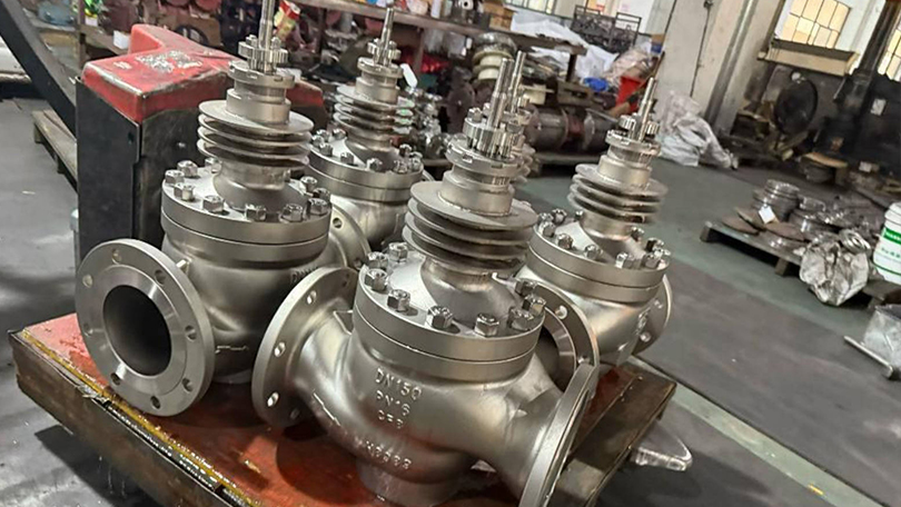
Control Valve

Conclusion

Control valves are the essential final control elements that make automated process control possible across virtually every industrial sector. From simple pressure regulation in a water treatment plant to high-pressure let-down in a petrochemical refinery, control valves translate electronic control signals into precise physical adjustments of flow area, enabling stable, safe, and efficient process operation. The selection of the correct control valve type — whether globe-style for precise throttling, rotary ball for high capacity, high-performance butterfly for large diameters, cage-guided for severe services, or diaphragm for sanitary applications — depends on a careful evaluation of process conditions, fluid properties, performance requirements, and lifecycle cost.

Key considerations in any control valve selection include the required flow coefficient (Cv), pressure drop and cavitation risk, noise predictions, rangeability, material compatibility with the process fluid, actuator type and fail-safe configuration, and communication protocol compatibility. The Class 300 selection guide provided in this article serves as a practical reference for the most common industrial control valve applications, covering valve type selection by service condition and actuator sizing by valve size and type.

As industrial automation advances with digitalization, Industry 4.0, and the Industrial Internet of Things (IIoT), control valves are evolving from simple mechanical regulators into intelligent field devices with embedded diagnostics, predictive maintenance capabilities, and wireless communication. Smart positioners with HART, Foundation Fieldbus, and PROFIBUS PA protocols enable condition monitoring, valve signature analysis, and real-time performance tracking that reduce unplanned downtime and optimize maintenance intervals. Selecting a control valve today means choosing not just a mechanical device, but a smart instrument that will integrate with the plant’s digital infrastructure for years to come.

Vornet Valve manufactures a comprehensive range of control valves in carbon steel (WCB, WCC, LCB), stainless steel (CF8, CF8M, CF3M), and alloy steel (WC6, WC9), with sizes from NPS 1/2″ to 24″ and pressure classes from Class 150 to Class 2500. Vornet control valves are designed with standard and custom trim options including anti-cavitation, low-noise, and erosion-resistant configurations. All Vornet control valves are designed, manufactured, and tested in accordance with IEC 60534, ASME B16.34, and API 598 standards, ensuring reliable performance in the most demanding process control applications.

Need a Control Valve for Your Process System?

Vornet Valve manufactures control valves in carbon steel, stainless steel, and alloy steel — NPS 1/2″ to 24″, Class 150 to 2500. Pneumatic, electric, and hydraulic actuation available.

Get a Quote →

What Is a Globe Valve? Complete Guide to Types, Features, and Applications

📌 Quick Summary:

Globe valves regulate flow through linear motion of a disc against a stationary seat, making them ideal for throttling, frequent operation, and precise flow control. This guide covers Z-type, Y-pattern, angle, and bellows seal globe valves with selection criteria for pressure, temperature, and media compatibility.

📋 Key Takeaways

  • Globe valves regulate flow via linear motion of a disc against a stationary seat, offering precise throttling control.
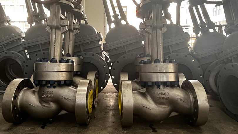
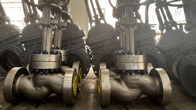
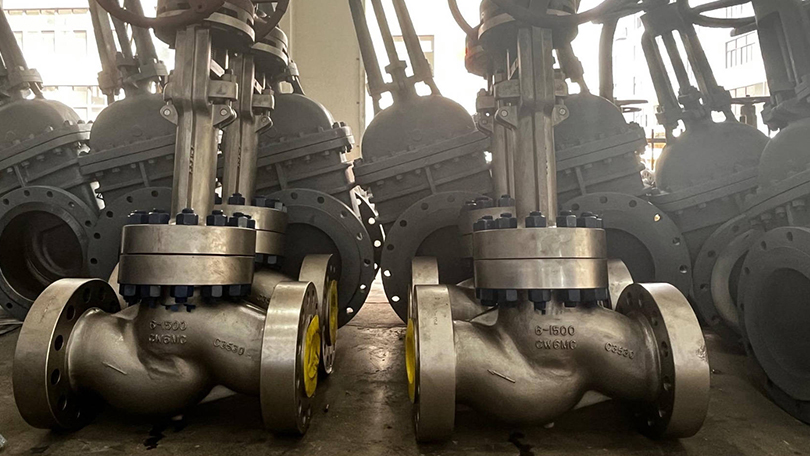
  • Z-type (tee-pattern) provides lowest cost but highest pressure drop; Y-pattern minimizes flow resistance for high-pressure service.
  • Angle-pattern globe valves eliminate an elbow fitting, while bellows-seal designs prevent stem leakage in hazardous fluids.
  • Needle valves offer fine flow regulation for instrumentation and small-bore applications with tapered disc-to-seat engagement.

however, This globe valve complete guide covers all major globe valve types including Z-type, Y-type, angle, bellows seal, and needle valves, with working principles, material selection, and sizing information for industrial applications.

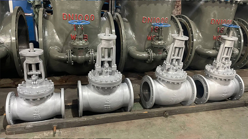
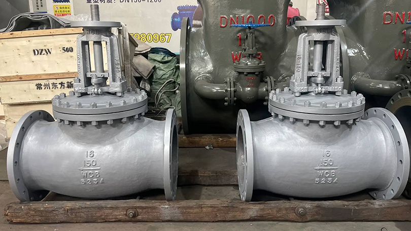
additionally, This globe valve complete guide covers all major types, working principles, and selection criteria for industrial applications. A globe valve is a linear motion valve used to regulate or throttle flow in a pipeline. Named for its spherical body shape — though modern designs vary — the globe valve operates using a movable disc (or plug) that seats against a stationary ring seat. By raising or lowering the disc through a handwheel, actuator, or stem, the operator can precisely control the flow rate from fully open to fully closed. Unlike gate valves, which are designed primarily for fully open or fully closed service, globe valves excel at throttling and flow regulation, making them one of the most widely used valve types in industrial piping systems. For a broader overview of how globe valves compare with other valve types, see our comprehensive industrial valve selection guide.

The defining characteristic of a globe valve is the change in flow direction through the valve body. Fluid entering the valve must flow around the seat and disc mechanism, creating a pressure drop that enables precise throttling control. This design inherently produces more resistance to flow than a gate or ball valve of the same size, but delivers superior control accuracy and shutoff capability.

Globe valves are manufactured in sizes from NPS 1/2″ to 48″ and pressure classes from Class 150 to Class 4500, in materials ranging from carbon steel to high-nickel alloys. They are governed by design standards including ASME B16.34, API 602 (for small forged steel valves), and BS 1873 (for flanged steel globe valves).

Globe Valve

Globe valve types: How Does a Globe Valve Work?

The operating principle of a globe valve is straightforward: a handwheel or actuator rotates the valve stem, which moves the disc (or plug) perpendicular to the seating surface. When the disc lifts away from the seat, flow passes through the annular opening between disc and seat. The distance the disc travels determines the size of this opening and therefore the flow rate.

Key operating characteristics include:

Linear Stem Movement. The stem moves in a straight line (in-and-out) rather than rotating. On rising-stem globe valves, the stem position visually indicates how far the valve is open. Multi-turn actuation is standard — typically 5 to 15 turns from fully closed to fully open depending on valve size and seat design.

Flow Direction. Globe valves are designed for flow under the disc (standard) or over the disc depending on service. In standard installation, flow enters below the disc so that when the valve is partially open, fluid lifts the disc away from the seat. This configuration provides better control during opening. For high-pressure drop services, flow-over-disc installation reduces seat erosion when the valve is nearly closed.

Throttling Precision. The disc-to-seat geometry of a globe valve allows the operator to make fine adjustments to flow. A 1/4-turn of the handwheel on a typical 2″ globe valve changes the flow area by a predictable, repeatable amount. This precision is unmatched by quarter-turn valves (ball, butterfly) in throttling applications.

Globe Valve Complete Guide: Types of Globe Valves

Globe valves are classified by body design, disc design, and bonnet configuration. Each type is optimized for specific pressure, temperature, and flow conditions. The five most common globe valve types are described below.

Globe Valve

1. Z-Type Globe Valve (Standard Pattern)

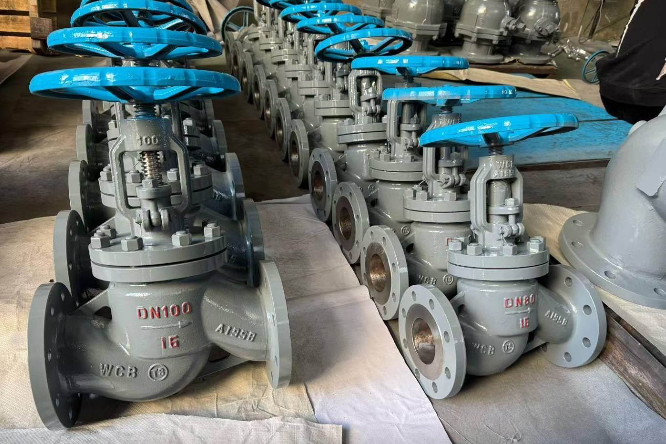
The Z-type or standard pattern globe valve features a characteristic Z-shaped flow path. Fluid enters below the disc, makes a 90-degree turn upward through the seat area, then turns another 90 degrees to exit the valve. This configuration creates the highest pressure drop among globe valve designs but also provides the best throttling characteristics. Z-type globe valves are the most common and economical choice for general throttling applications. They are widely used in water, steam, air, and general process services across various industrial applications at pressures up to Class 600 and temperatures up to 425°C. Available in sizes NPS 1/2″ to 24″ with threaded, flanged, or butt-weld end connections.

2. Y-Type Globe Valve (High Pressure)

Y-type globe valves have the seat and stem angled at approximately 45 degrees relative to the pipeline axis (forming a Y shape). This straight-through flow path significantly reduces pressure drop compared to Z-type designs. Y-type globe valves are the preferred choice for high-pressure and high-temperature services, particularly in power generation and steam systems where pressure drop must be minimized. They are commonly specified for boiler feedwater isolation, main steam lines, and turbine bypass applications. The Y-type design also reduces seat erosion in high-velocity services because the flow path is less tortuous. Pressure classes up to Class 4500 and sizes up to NPS 24″ are available.

3. Angle Globe Valve

Angle globe valves combine a globe valve body with a 90-degree turn, serving as both a valve and a pipe fitting. The inlet and outlet are at right angles, eliminating the need for a separate elbow fitting. This design reduces the number of potential leak points, lowers installation cost, and minimizes pressure drop compared to a Z-type globe valve with a separate elbow. Angle globe valves are commonly used in boiler feedwater systems, heater drain applications, and high-pressure let-down stations where space is constrained. They are also preferred for cyclic service where the valve experiences frequent opening and closing, as the angle body reduces thermal and mechanical stress on the piping.

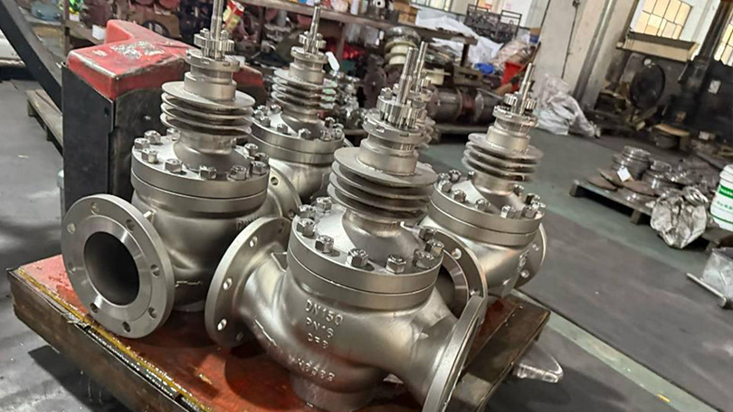
4. Bellows Seal Globe Valve

Bellows seal globe valves incorporate a metal bellows assembly between the stem and the bonnet, creating a leak-tight seal that prevents process fluid from escaping through the stem packing. The bellows are typically made from austenitic stainless steel (AISI 316L or 316Ti) or Inconel alloys and are welded to the stem at one end and the bonnet connection at the other. The primary advantage is zero fugitive emissions — these valves meet the most stringent environmental regulations including TA-Luft (Germany) and EPA Method 21 (USA). Bellows seal globe valves are essential in applications handling toxic, hazardous, flammable, or expensive fluids. They are widely used in chemical processing, pharmaceutical manufacturing, thermal oil systems, heat transfer fluid circuits, and steam systems where stem leakage cannot be tolerated. A secondary backup packing is usually provided above the bellows for added safety.

5. Needle Valve (Small Bore Globe Valve)

Needle valves are small globe valves (typically NPS 1/2″ and smaller) that use a tapered, needle-shaped disc for precise flow regulation. The needle disc fits into a matching conical seat, allowing extremely fine adjustment of the flow orifice. Needle valves are used primarily in instrumentation, sampling systems, chemical injection, and hydraulic control circuits where precise flow metering is required. They are available with threaded, compression, or tube-weld end connections in materials including 316 stainless steel, Monel, and Hastelloy. Maximum operating pressure can exceed 10,000 PSI (Class 6000+) for high-pressure instrumentation applications.

Globe Valve

Globe Valve vs. Gate Valve: Key Differences

Gate valves and globe valves are both linear motion valves but are designed for fundamentally different purposes. Understanding the distinctions is critical for proper valve selection.

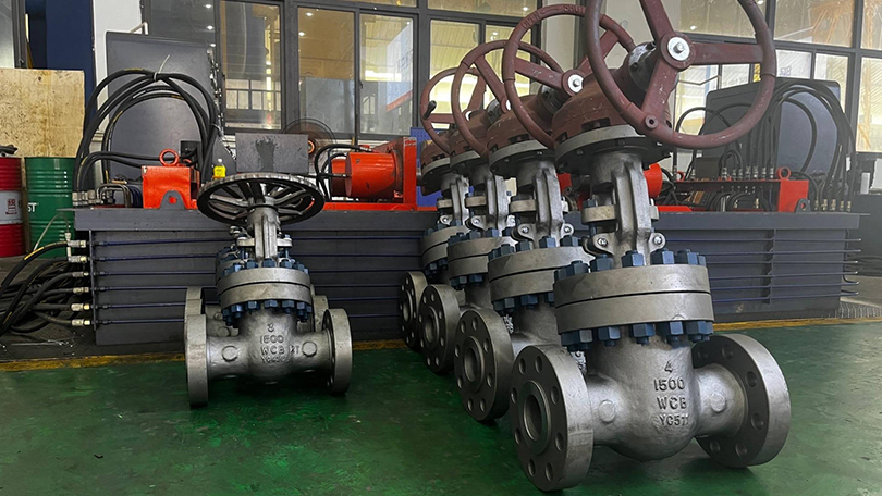
CharacteristicGlobe ValveGate Valve
Primary FunctionThrottling and flow regulationIsolation (fully open or fully closed)
Flow PathTortuous (changes direction inside body)Straight-through (full bore)
Pressure DropModerate to high (10-30% of inlet pressure)Very low (nearly zero when fully open)
Throttling CapabilityExcellent — precise control at any positionPoor — causes seat erosion if used for throttling
Shutoff TightnessVery good — suitable for bubble-tight shutoffExcellent — wedge gate design provides tight seal
Operating SpeedMulti-turn (5-15 turns depending on size)Multi-turn (10-30 turns depending on size)
Flow Capacity (Cv)Lower for same pipe sizeHigher for same pipe size
Water Hammer RiskLower — gradual closure characteristicsHigher — can trap fluid in gate cavity
Seat ErosionModerate — flow impinges on seatHigh (when partially open) — wire drawing on seat
Typical CostModerate (more complex body casting)Lower (simpler body design)
Preferred ServiceControl, regulation, frequent cyclingIsolation, infrequent operation

The rule of thumb in valve selection: if the application requires flow control or throttling, choose a globe valve. If the application requires isolation with minimal pressure drop, choose a gate valve. Attempting to use a gate valve for throttling will quickly erode the seating surfaces, leading to leakage and premature failure.

Globe Valve

Applications by Industry

Globe valves are used across virtually every industrial sector that handles pressurized fluids. Their throttling capability and reliable shutoff make them indispensable in the following industries:

Oil and Gas. In upstream production, globe valves regulate flow from wellheads, control injection rates for waterflood and gas lift operations, and provide precision flow control in gathering systems. In midstream pipelines, they serve as control valves at pump stations and metering skids. In downstream refineries, globe valves are used for process control on crude distillation units, catalytic crackers, hydrotreaters, and product blending systems. Materials typically include WCB carbon steel for sweet service and CF8M stainless steel or WC6 alloy steel for sour and elevated-temperature services.

Power Generation. Power plants are the single largest application for high-pressure globe valves, particularly Y-type and angle designs. Globe valves control boiler feedwater flow, regulate steam extraction from turbines, provide condensate system control, and serve as turbine bypass valves. The ability to withstand high temperatures (up to 600°C) and pressures (up to Class 4500) makes Y-type globe valves standard equipment in supercritical and ultra-supercritical power plants.

Chemical and Petrochemical. Chemical processing requires precise flow control of reactants, catalysts, and intermediates. Globe valves with bellows seals are used extensively for toxic and hazardous chemicals. Needle valves provide fine metering for catalyst injection and additive dosing. Materials of construction range from 316L stainless steel for general chemical service to Hastelloy C276 and Monel for highly corrosive media such as hydrochloric acid, wet chlorine, and seawater.

Water and Wastewater. Municipal water treatment plants use globe valves for filter backwash control, chemical dosing (chlorine, fluoride, coagulants), and flow regulation in distribution systems. Wastewater treatment plants use globe valves for sludge handling, aeration control, and digester gas systems. Sizes typically range from NPS 2″ to 24″ in Class 150 and Class 300.

HVAC and Building Services. Globe valves are standard equipment in heating, ventilation, and air conditioning systems for controlling hot water, chilled water, and steam flow to coils, radiators, and heat exchangers. Their throttling precision makes them ideal for temperature control in large commercial buildings, hospitals, and data centers.

Pharmaceutical and Food Processing. In pharmaceutical and food-grade applications, globe valves with sanitary connections (clamp ends) and electropolished internal surfaces meet FDA and cGMP requirements for clean-in-place (CIP) and sterilize-in-place (SIP) operations. Materials are typically 316L stainless steel with PTFE or EPDM seat seals.

Material Selection for Globe Valves

The choice of body, bonnet, and trim materials for a globe valve is driven by operating conditions and fluid compatibility. The table below provides a selection guide for common globe valve materials per ASME B16.34 standards.

Material GradeASTM SpecMax TemperatureBest For
WCB (Carbon Steel)A216425°C (800°F)Water, oil, gas, steam — general purpose
WCC (Carbon Steel)A216425°C (800°F)Lower temperature services, better weldability than WCB
CF8 (304 SS)A351425°C (800°F)Corrosive media, food processing, nitric acid
CF8M (316 SS)A351425°C (800°F)Marine, chemical, chloride-containing services
WC6 (1.25Cr-0.5Mo)A217540°C (1000°F)Steam, high-temperature hydrocarbon processing
WC9 (2.25Cr-1Mo)A217595°C (1100°F)High-temperature steam, hydrogen service, creep-resistant
LCB (Low-temp Carbon)A352−46°C (−50°F)Cryogenic and cold-weather applications
LC3 (3.5% Nickel)A352−101°C (−150°F)Low-temperature natural gas processing

Trim Material Guidelines: For standard water and steam service at moderate temperatures, 13% chromium stainless steel (13Cr, A276 Type 410) is the standard disc and seat material. For corrosive services, specify 316 stainless steel trim. For high-temperature or high-velocity services where seat erosion is a concern, Stellite 6 (cobalt-based alloy) hardfacing on both the disc and seat ring provides superior wear resistance. For sour gas services per NACE MR0175/ISO 15156, trim materials must be limited to 22 HRC maximum hardness.

Installation Best Practices

Proper installation is essential for achieving the rated performance and service life of a globe valve. The following best practices should be observed:

Flow Direction. Globe valves have a marked flow direction arrow on the body. Most standard globe valves are designed for flow under the disc — the pressure lifts the disc away from the seat during opening, reducing operating torque. Installing a globe valve backward can cause the disc to lift off the seat under high pressure differentials, leading to loss of control and potential seat damage.

Orientation. Globe valves should be installed with the stem vertical or nearly vertical. For high-temperature steam applications (>400°C), the stem should be in the vertical position to prevent thermal binding and uneven thermal expansion of internal components. For horizontal pipelines, stem-up installation is standard, with the bonnet accessible for maintenance.

Pipe Support. Globe valves are heavier than equivalent gate or ball valves due to the thicker body walls and internal baffle. Ensure adequate pipe supports are installed on both sides of the valve to prevent excessive stress on the body and flange connections. For valves NPS 8″ and larger, consider independent valve supports rather than relying solely on pipe hangers.

Allow for Thermal Expansion. In high-temperature services (>300°C), thermal expansion of the piping system can impose additional stress on the valve end connections. Use flexible expansion joints or loops where necessary, and ensure flanged connections have adequate bolt stretch to maintain gasket compression at operating temperature.

Stem Protection. Globe valve stems are exposed and can be damaged during installation. Protect the stem from impact, weld spatter, and construction debris. Do not use the handwheel or actuator as a lifting point — use the designated lifting lugs or body sling points.

Gasket Selection. For flanged globe valves, select gasket materials compatible with the operating temperature and fluid. Spiral-wound gaskets with 316SS windings and flexible graphite filler are standard for most industrial services. For high-temperature steam, use spiral-wound gaskets with heat-treated filler rings. For low-temperature or cryogenic service, PTFE envelope gaskets may be preferred.

Selection Criteria for Globe Valves

Selecting the right globe valve requires systematic evaluation of the following factors:

1. Service Conditions. Determine the operating pressure, temperature, and fluid characteristics (clean, dirty, corrosive, viscous, hazardous). These parameters define the pressure class, body material, and trim requirements.

2. Flow Control Requirements. Evaluate the required Cv (flow coefficient), turndown ratio, and control characteristics. For applications requiring a wide range of flow rates (turndown > 10:1), specify a globe valve with a characterized disc (equal percentage or linear) or a cage-guided design for precise flow curve matching.

3. Shutoff Class. Globe valves are available with metal seats (Class IV per FCI 70-2 / ANSI/FCI 70.2) and soft seats (Class VI). Specify Class IV for general steam and high-temperature service. Specify soft-seat (PTFE or PEEK) Class VI for bubble-tight shutoff in gas, chemical, or fugitive-emission-sensitive applications.

4. End Connections. Flanged (RF or RTJ per ASME B16.5) for general service up to Class 2500. Butt-weld ends per ASME B16.25 for high-pressure, high-temperature service where flanged connections are not preferred. Threaded ends (NPT) for small-bore valves NPS 2″ and smaller. Socket-weld ends for small-bore, high-pressure service.

5. Actuation. Choose manual handwheel for infrequent operation and throttling. Choose gear-operated handwheel for valves NPS 8″ and larger or when operating torque exceeds 150 Nm. Choose pneumatic actuation for remote control and automated process systems. Choose electric actuation for precise positioning in SCADA-controlled facilities.

6. Fugitive Emission Requirements. For applications handling toxic, hazardous, or volatile fluids, specify bellows seal globe valves or valves with low-emission packing (graphite or PTFE chevron rings) meeting TA-Luft or ISO 15848-1 requirements.

Globe Valve Class 300 Selection Guide

Class 300 globe valves are the most commonly specified pressure class for industrial globe valve applications. Rated at 740 PSI (5.1 MPa) at 100°F per ASME B16.34, Class 300 globe valves offer an optimal balance of pressure capability, cost, and availability for the majority of process, power, and general industrial applications.

Class 300 Globe Valve Specifications at a Glance

SpecificationClass 300 Globe Valve
Pressure Rating @ 100°F740 PSI (5.1 MPa) — ASME B16.34
Size RangeNPS 1/2″ — 24″ (DN 15 — 600)
Body MaterialsWCB (A216), WC6 (A217), CF8M (A351), LCB (A352)
Bonnet DesignBolted bonnet, pressure seal bonnet (high-temp), welded bonnet (small bore)
End ConnectionsFlanged RF (ASME B16.5), Butt-Weld (ASME B16.25), Socket-Weld, Threaded
Design StandardBS 1873, ASME B16.34, API 602 (forged small bore)
Trim Options13Cr (A276 410), 316 SS, Stellite 6 hardfaced seat & disc
OperationHandwheel, gearbox, pneumatic actuator, electric actuator
Test StandardAPI 598 (hydrostatic shell, seat, backseat tests)
Leakage ClassClass IV (metal seat) or Class VI (soft seat) per FCI 70.2

Class 300 Globe Valve Selection by Service

Service ConditionRecommended TypeBody MaterialTrim
Water, air & general utilityZ-Type Globe ValveWCB (A216 Gr. WCB)13Cr / F6a
Steam up to 425°CZ-Type or Y-TypeWCB or WC613Cr + Stellite 6 seat
High-pressure steam >425°CY-Type Globe ValveWC9 (A217 Gr. WC9)Stellite 6 seat & disc
Hydrocarbon / refined oilZ-Type Globe ValveWCB or LCB13Cr / 316 SS overlay
Corrosive chemicalsZ-Type Bellows SealCF8M (A351 Gr. CF8M)316 SS / Alloy 20
HVAC / building servicesZ-Type Globe ValveWCB / Ductile Iron13Cr or PTFE soft seat
Toxic / hazardous fluidsBellows Seal Globe ValveWCB or CF8M316 SS + Stellite seat
Instrumentation / meteringNeedle Valve316 SS (A479)316 SS / Stellite tip

Class 300 is the most widely specified pressure class for globe valves across refining, petrochemical, power generation, and general industrial applications. When selecting, confirm that the body material is suitable for the minimum design temperature (MDMT) and that the trim materials are compatible with the process fluid chemistry. For services involving thermal cycling (frequent start/stop), Y-type and angle globe valves provide superior resistance to thermal fatigue compared to Z-type designs.

Globe Valve

Conclusion

Globe valves are essential flow control components in virtually every industrial fluid handling system. Their ability to provide precise, repeatable throttling — combined with reliable shutoff capability — makes them the valve of choice when control matters more than conductance. The five main types — Z-type standard, Y-type high-pressure, angle globe, bellows seal, and needle valve — cover the full spectrum of industrial applications from low-pressure HVAC circuits to supercritical power plant steam lines.

When selecting a globe valve, the primary decision criteria are: operating pressure and temperature (determining the Class and body material), throttling precision requirements (determining the disc and seat design), fluid compatibility (determining trim materials and seal type), and end connection compatibility with the existing piping system. The Class 300 selection guide provided in this article serves as a practical reference for the most common industrial globe valve applications.

Vornet Valve manufactures a comprehensive range of globe valves in carbon steel (WCB, WCC, LCB), stainless steel (CF8, CF8M, CF3M), and alloy steel (WC6, WC9), with sizes from NPS 1/2″ to 24″ and pressure classes from Class 150 to Class 2500. All Vornet globe valves are designed, manufactured, and tested in accordance with BS 1873, ASME B16.34, API 602, and API 598 standards, ensuring reliable performance in the most demanding industrial services.

Frequently Asked Questions

Q1: What is the main difference between a globe valve and a gate valve?
A globe valve is designed for throttling and flow regulation, using a disc that moves perpendicular to the seat to precisely control flow. A gate valve is designed for isolation (fully open or fully closed), using a wedge that slides in and out of the flow path. Globe valves create a significant pressure drop but offer excellent control; gate valves have minimal pressure drop when fully open but must not be used for throttling as it causes seat erosion and leakage.

Q2: Why is it called a globe valve?
The name comes from the original body design, which featured a spherical (globe-shaped) central chamber that housed the seat and disc mechanism. While modern globe valves may have different exterior shapes, the internal structure — a baffle with a circular seat that creates a change in flow direction — retains the globe valve name. The spherical body shape provided optimal pressure containment for the disc and seat assembly.

Q3: Can a globe valve be used for isolation (on/off) service?
Yes, globe valves can be used for isolation service and provide very good shutoff, particularly with soft seats that achieve bubble-tight Class VI shutoff. However, for applications where the valve is rarely operated and minimum pressure drop is required, a gate valve is the better choice. For applications that require both throttling and positive shutoff in the same valve — such as bypass circuits and control stations — a globe valve is the appropriate selection.

Q4: What does the pressure drop across a globe valve depend on?
The pressure drop across a globe valve depends on the valve size (flow area), the disc position (how far open the valve is), the flow rate (GPM or LPM), and the specific gravity of the fluid. For a fully open globe valve, the pressure drop is typically 10-30% of the inlet pressure, compared to 1-3% for a fully open gate valve. The Cv (flow coefficient) published by the manufacturer is used to calculate the exact pressure drop at a given flow rate using the formula: ΔP = SG × (Q / Cv)², where Q is flow rate and SG is specific gravity.

Q5: What is the maximum operating temperature for globe valves?
The maximum temperature depends on the body material and seat type. Standard carbon steel (WCB) globe valves are rated to 425°C (800°F). Alloy steel WC6 (1.25Cr-0.5Mo) extends this to 540°C (1000°F). Alloy steel WC9 (2.25Cr-1Mo) reaches 595°C (1100°F). For metal-seated globe valves with Stellite hardfacing, continuous operation at 595°C is achievable. For services above 595°C, special high-temperature alloys such as Inconel 625 or AISI 310 stainless steel are required, and valve design must account for reduced material strength at elevated temperatures per ASME B16.34 derating curves. All material specifications reference ASTM International standards.

Q6: How do I select between a Z-type and a Y-type globe valve?
Select a Z-type globe valve for general throttling applications where some pressure drop is acceptable and cost is a primary consideration. Select a Y-type globe valve for high-pressure (>Class 600) or high-temperature (>400°C) applications where pressure drop must be minimized, particularly in boiler feedwater, main steam, and turbine bypass systems. Y-type globe valves cost approximately 20-40% more than equivalent Z-type valves but offer 30-50% lower pressure drop and significantly better resistance to thermal fatigue and seat erosion in severe service conditions.

Q7: When should I specify a bellows seal globe valve?
Specify a bellows seal globe valve whenever the process fluid is toxic, flammable, hazardous, expensive, or environmentally regulated. Bellows seal globe valves are mandatory in many jurisdictions for applications handling benzene, hydrogen sulfide, chlorine, phosgene, thermal oil (heat transfer fluids), and other fugitive-emission-sensitive media. They are also recommended for steam systems where stem leakage would cause safety hazards or energy losses. Bellows seal valves meet TA-Luft and EPA Method 21 fugitive emission standards and provide zero measurable leakage from the stem seal for the life of the bellows (typically 10,000+ cycles).

Q8: What maintenance is required for globe valves in industrial service?
Routine maintenance includes: (1) Periodic stem seal adjustment — tighten packing nuts gradually as the packing wears, but avoid over-tightening which increases operating torque; (2) Seat leak testing — perform during each plant turnaround to verify shutoff integrity; (3) Disc and seat ring inspection — check for pitting, galling, wire drawing, and erosion, particularly on the downstream seat face; (4) Stem thread lubrication — apply high-temperature anti-seize lubricant to stem threads annually; (5) Bellows integrity testing — for bellows seal valves, perform a pressure test on the bellows chamber at each turnaround; (6) Gasket replacement — replace bonnet gasket whenever the valve is disassembled for internal inspection. For severe service applications (high-temperature steam, erosive fluids), inspection frequency should be increased to every 6-12 months.

For inquiries about globe valve selection, technical quotation, custom manufacturing, or bulk procurement of Class 150 to Class 2500 globe valves, contact our engineering team.

Need a Globe Valve for Your Application?

Vornet Valve manufactures a comprehensive range of globe valves in carbon steel, stainless steel, and alloy steel — Z-type, Y-type, angle, bellows seal, and needle valves — from Class 150 to Class 2500, NPS 1/2″ to 24″. All designed to BS 1873, ASME B16.34, and API 602 standards.

💬 WhatsApp Us✉ Email Us

📖 Related Guides:
Globe Valve Selection Guide
API 600 Gate Valve vs Globe Valve
Control Valve Selection Guide

🏭 Looking for a Reliable Globe Valve Manufacturer?

Vornet Valve is a China-based industrial valve manufacturer with over 20 years of experience. We manufacture globe valves to BS 1873, ASME B16.34, and API 602 standards — including Z-type, Y-pattern, angle, bellows seal, and needle globe valves. Available in sizes NPS 1/2″ to 24″, Class 150 to Class 2500, with materials from WCB carbon steel to Hastelloy C276. Our globe valves are used in oil & gas, power generation, chemical processing, and water treatment applications worldwide.

Contact us today for a quote or technical consultation:

What Is a Pigging Valve? Complete Guide to Pipeline Cleaning Valves

📋 Key Takeaways

  • Pigging valves enable pipeline cleaning pigs to pass through without interrupting flow or requiring a traditional launcher.
  • Full-bore through-conduit design with equal internal diameter ensures unobstructed pig passage and minimal pressure drop.
  • Pigging valves eliminate the need for launcher barrels, reducing system footprint and capital expenditure.
  • Key applications include oil & gas pipelines, chemical processing, and water injection systems requiring regular internal cleaning.

Pigging valve types: Pigging Valve for Pipeline Cleaning: What Is a Pigging Valve

furthermore, A pigging valve for pipeline cleaning is a specialized industrial valve that functions as both a launcher and receiver for pipeline cleaning pigs — devices that travel through pipelines to remove debris, wax, scale, and product buildup. Instead of requiring a separate pig barrel, closure door, vent system, and support piping, a pigging valve combines all these functions into a single inline valve body.

additionally, For operators of long-distance pipelines transporting crude oil, natural gas, refined products, water, or chemicals, the pigging valve represents a significant reduction in both capital expenditure and operational complexity. A single valve replaces what traditionally required a dedicated pig launcher station occupying 5-10 meters of pipeline right-of-way.

The term “pigging” comes from the squealing sound the original leather-and-metal cleaning devices made as they traveled through pipes. Modern pigs are sophisticated tools made from polyurethane foam or molded rubber, often fitted with sensors for pipeline inspection. The pigging valve is designed to launch and receive these tools without interrupting pipeline flow.

How Does a Pigging Valve Work?

The pigging valve uses a full-bore ball or plug design. When fully open, the bore diameter matches the pipeline inner diameter exactly, creating an unobstructed passage for the pig. The valve body includes a side entry port for loading and unloading pigs.

The pigging cycle follows these steps:

pigging valve for pipeline cleaning - Pigging valve pipeline cleaning equipment

Step 1 — Loading: With the valve in the closed position, the side entry port is opened and the pig is inserted into the valve chamber. The port is then sealed.

Step 2 — Launch: The valve opens to the full-bore position. Pipeline pressure pushes the pig out of the valve chamber and into the pipeline. The pig travels downstream at the speed of the flowing medium.

Step 3 — Recovery: At the receiving end, a second pigging valve in the closed position catches the pig as it arrives. The valve is isolated, the side port is opened, and the pig is removed.

Step 4 — Return to Service: The valve closes, the port is sealed, and the valve returns to normal pipeline isolation or flow control service.

A full pigging cycle — from loading to recovery — takes approximately 10-15 minutes. Traditional pig launcher systems require 2-4 hours for the same operation, plus setup and teardown time for lifting equipment.

Pigging Valve vs. Traditional Pig Launcher

Understanding the differences between a pigging valve and a traditional pig launcher system is essential for pipeline operators evaluating equipment upgrades. The table below compares the two approaches across the key decision factors:

FactorPigging ValveTraditional Pig Launcher
FootprintSingle inline valve, < 1m length3-10m barrel assembly + closure door swing area
Capital Cost$2,000-$15,000 depending on size and class$8,000-$50,000+ including barrel, closure, vent, drain, support structure
InstallationWelded or flanged inline, no foundation requiredConcrete foundation, structural steel supports, multiple weld joints
Operators Required1 person2-3 persons (operators + lifting equipment operator)
Cycle Time10-15 minutes2-4 hours
MaintenanceStandard valve seat/seal replacementClosure seal replacement, vent valve servicing, barrel internal inspection
Safety RiskLower — no large-diameter pressure closureHigher — large closure door under pressure is a known failure point
Dual FunctionServes as isolation valve when not piggingDedicated pigging only

pigging valve for pipeline cleaning - Pigging valve vs traditional launcher comparison

For new pipeline installations, the cost savings from choosing pigging valves over traditional launchers can reach 40-60% on the pigging equipment alone, not counting installation and foundation savings.

Key Applications and Industries

Pigging valves are used across multiple industries where pipeline cleaning is a routine operational requirement:

Oil & Gas Transmission. Crude oil pipelines accumulate paraffin wax deposits that reduce flow capacity over time. Natural gas pipelines collect liquid condensate, black powder (iron sulfide), and debris from construction. Regular pigging with a pigging valve maintains flow efficiency and prevents blockage. Typical pigging frequency ranges from weekly to quarterly depending on medium composition.

Refined Products Pipelines. Product pipelines that transport gasoline, diesel, jet fuel, and LPG require batch separation pigs between different product runs. A pigging valve at the receiving end allows operators to detect product interface and divert batches to the correct tank without cross-contamination.

Water and Wastewater. Municipal water transmission pipelines develop biofilm, scale (calcium carbonate), and sediment over time. Pigging restores flow capacity by 15-30% in many cases, deferring the need for pipe replacement. Pigging valves are particularly valuable in water systems where shutdown for cleaning is politically and logistically difficult.

Chemical Processing. Chemical plants transfer acids, solvents, polymers, and intermediates between storage tanks and processing units. Product purity requirements make regular pigging mandatory. Pigging valves allow chemical operators to clean lines between batch changes without opening the system to atmosphere.

Petrochemical and Refining. Refinery transfer lines handling crude, intermediates, and finished products benefit from pigging valves at launcher and receiver locations. The ability to pig without full system shutdown is especially valuable in continuous-process refineries where unscheduled downtime costs $100,000+ per day.

pigging valve for pipeline cleaning - Pigging valve technical specifications

Technical Specifications and Design Standards

Vornet Valve manufactures pigging valves to the following specifications, compliant with international standards:

ParameterSpecification
Size Range2″ – 16″ (DN50 – DN400)
Pressure RatingClass 150 – 2500 (PN16 – PN420)
Body MaterialsCarbon steel (WCB/WCC), stainless steel (CF8/CF8M), alloy steel, duplex stainless steel, nickel-based alloys (Monel, Hastelloy, Inconel)
End ConnectionsRF flanged (ASME B16.5), BW butt-weld (ASME B16.25), NPT threaded, SW socket-weld
OperationManual gearbox, pneumatic actuator, electric actuator, hydraulic actuator
Design StandardAPI 6D / ASME B16.34
Pressure TestingAPI 6D / ISO 5208 Rate A (zero-leakage)
Temperature Range-46°C to +425°C (higher with special materials)
Bore DesignFull bore (full opening, piggable)
Sour ServiceNACE MR0175 / ISO 15156 compliant available

The full-bore design is the critical feature that makes a pigging valve suitable for pipeline cleaning. Standard reduced-bore ball valves have a smaller internal diameter that blocks pig passage. Always verify the bore diameter matches the pipeline ID before specifying a pigging valve.

How to Select the Right Pigging Valve

Selection of a pigging valve requires evaluation of several factors specific to the pipeline and operating conditions:

1. Pipeline Diameter and Schedule. The valve bore must match the pipe inner diameter. For a 6″ Schedule 40 pipe (ID = 6.065″), specify a 6″ full-bore pigging valve. If the pipeline uses Schedule 80 (ID = 5.761″), a 6″ valve still works, but confirm the pig size matches the smaller ID.

2. Operating Pressure. Select a pressure class that exceeds the maximum allowable operating pressure (MAOP) including surge. For a pipeline rated at 600 PSIG, a Class 300 valve (720 PSIG at 100°F) provides adequate margin. For sour gas pipelines over 1,000 PSIG, Class 600 or higher is typical.

3. Pig Type and Frequency. Foam pigs (light cleaning, drying) require less valve wear than brush or magnetic pigs (heavy cleaning). For daily pigging with aggressive pigs, specify hardened seat inserts and replaceable seal carriers to extend service life between maintenance intervals.

4. Medium Compatibility. For sweet crude and gas, carbon steel body with standard trim (13Cr or F6NM) is sufficient. For sour service (H2S present), NACE MR0175 compliance requires controlled hardness materials — typically LCC or LCB body with Inconel 625 overlay on sealing surfaces. For chemical service, verify compatibility with the specific chemical concentration and temperature.

5. Actuation Requirements. Manual gear operation is suitable for pigging frequencies of once per week or less. For daily pigging or remote/unmanned stations, specify pneumatic or electric actuation with position feedback and remote control capability.

6. Temperature Range. Standard pigging valves with PTFE seats operate from -46°C to +200°C. For high-temperature pipelines (steam, hot oil, superheated fluids), specify PEEK seats (up to 260°C) or metal seats (up to 425°C). For cryogenic service (LNG, ethylene below -100°C), extended bonnet designs with low-temperature trim are required.

Installation and Maintenance Considerations

Pigging valves install directly in the pipeline like a standard full-bore valve. No special foundation or structural support is required beyond what is standard for the pipeline class. Key installation points:

— Orient the side entry port accessible for pig loading/unloading. For horizontal pipelines, the port should face upward or to the side with clearance for pig insertion tools.

— Provide a downstream receiver valve at the pig retrieval location. The distance between launcher and receiver depends on the pipeline length and pig travel speed.

— Install pressure gauges upstream and downstream of the pigging valve to monitor differential pressure during pig passage. A sudden pressure drop indicates the pig has exited the valve.

Routine maintenance for pigging valves follows the same schedule as standard full-bore ball valves. Seat seal inspection every 12 months or 500 pigging cycles, whichever comes first. Side port seals should be inspected every 100 cycles. Grease fittings on the gearbox should be serviced annually.

FAQ: Pigging Valves

Q1: Can a pigging valve be used as a regular isolation valve?
A: Yes. When not in use for pigging operations, the pigging valve functions as a standard full-bore ball valve for flow isolation, with the same pressure and sealing performance as any API 6D-compliant valve.

Q2: What is the maximum pigging frequency a pigging valve can handle?
A: Vornet pigging valves with standard PTFE seats are rated for daily pigging cycles. For higher frequencies (multiple pigs per day), specify hardened seat inserts and replaceable seal carriers. With proper maintenance, the valve body itself lasts the full pipeline design life of 20-30 years.

Q3: How does a pigging valve handle different pig types?
A: The full-bore design accommodates all standard pig types: foam cleaning pigs, cup pigs, disc pigs, magnetic cleaning pigs, and intelligent inspection pigs (smart pigs). The minimum bore diameter must clear the largest pig component. For smart pigs with sensors and electronics, a bore 1″ larger than the pig diameter is recommended.

Q4: What is the cost difference between a pigging valve and a traditional launcher?
A: For a 10″ Class 600 application, a pigging valve costs approximately $8,000-$12,000. A complete traditional pig launcher station (barrel, closure, vent, drain, support structure, foundation) costs $25,000-$50,000 installed. The pigging valve saves 50-70% on initial equipment cost and eliminates ongoing maintenance for closure seals, vent valves, and barrel internal coating.

Q5: Are pigging valves available for sour gas service (NACE MR0175)?
A: Yes. Vornet Valve supplies pigging valves with NACE MR0175 / ISO 15156 compliance for sour gas and oil services. This includes controlled hardness materials, Inconel 625 or 825 overlay on sealing surfaces, and certification with material test reports (MTRs).

Q6: Can a pigging valve be retrofitted into an existing pig launcher station?
A: Yes. The pigging valve replaces the traditional launcher barrel and closure directly. The existing pipeline connections typically match the pigging valve end connections. Retrofit installation can be completed within a single day during a planned shutdown, with immediate reduction in future pigging cycle time.

Q7: What is the temperature limit for pigging valves?
A: Standard PTFE-seated pigging valves operate from -46°C to +200°C. PEEK seats extend the range to 260°C. Metal-seated designs handle up to 425°C. For cryogenic service below -46°C, extended bonnet designs with low-temperature trim (F316 stainless steel, PCTFE seats) are available.

Q8: How do I verify the pigging valve bore matches my pipeline?
A: Request the valve’s actual bore diameter from the manufacturer. For Vornet pigging valves, the bore is 1-2 mm larger than the nominal pipe inside diameter per API 6D full-bore requirements. Provide your pipe schedule (e.g., 8″ Sch 40, ID = 7.981″) and the manufacturer will confirm the valve bore clearance for your specific pig size.

For technical support, specifications, or a quotation for pigging valves for your pipeline project, contact our engineering team. We provide drawings, material certifications, and application engineering support for all pigging valve orders. For more valve selection resources, visit our Valve Selection Guide. All material specifications reference ASTM International standards.

Need a Pigging Valve for Your Pipeline?

Vornet Valve supplies pigging valves in sizes 2″ to 16″, Class 150 to 2500, in carbon steel, stainless steel, duplex, and alloy materials. Contact our engineering team for sizing and specification assistance.

Request a Quote →
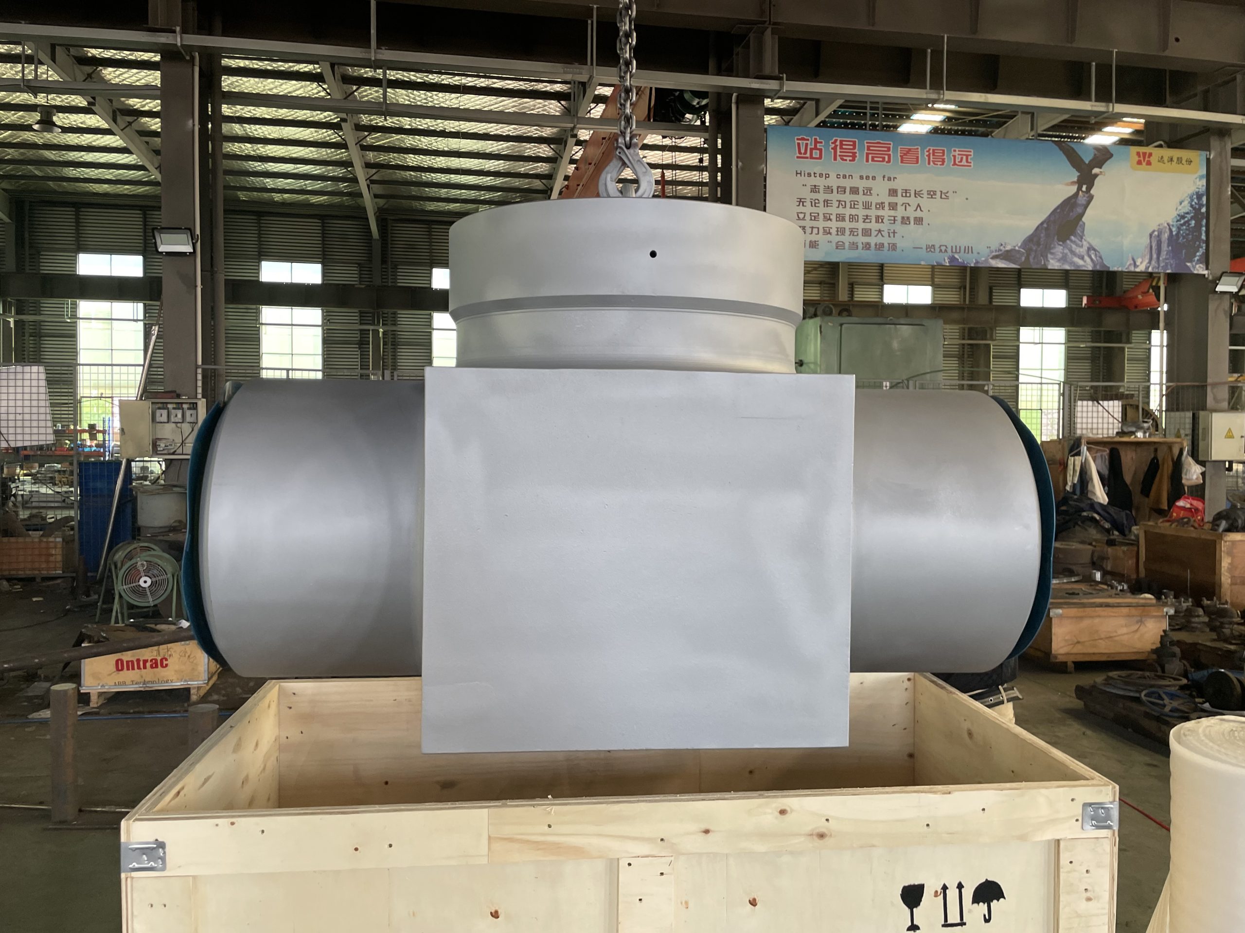
Slab Gate Valve: Complete Guide to Features, Design, and Applications

📋 Key Takeaways

  • Slab gate valves feature a flat through-conduit gate providing full-bore flow and bidirectional sealing capability.
  • Double-sealing design with upstream and downstream seats isolates pipeline pressure for safe maintenance.
  • Sealant injection ports allow emergency seat sealing without valve disassembly in the field.
  • Primarily used in oil and gas pipelines, pigging operations, and high-pressure transmission systems requiring tight shut-off.

however, This slab gate valve guide covers a slab gate valve is a type of through-conduit gate valve that uses a flat, rectangular gate (the “slab”) that moves perpendicular to the flow path to open or close the valve. Unlike wedge gate valves that rely on a tapered wedge for sealing, slab gate valves use a parallel-face gate that slides between two seat rings to provide a tight shutoff.

Slab gate valves are specifically designed for pipeline applications requiring full bore flow with minimal pressure drop and reliable bi-directional sealing. They are widely used in oil and gas transmission pipelines, where their through-conduit design allows pipeline cleaning pigs and inspection tools to pass through the valve without obstruction.

Slab Gate Valve parallel gate design showing the flat rectangular gate

Through conduit gate valve: Key Features of Slab Gate Valves

1. Through-Conduit Design

Furthermore, the most distinguishing feature of a slab gate valve is its through-conduit (full bore) design. When fully open, the gate retracts completely into the bonnet cavity, leaving an unobstructed bore that matches the pipeline internal diameter. This allows pipeline pigs, scrapers, and intelligent inspection tools to pass through the valve without restriction.

2. Parallel Slab Gate

therefore, The gate itself is a flat, rectangular slab with a circular opening. The parallel faces of the slab are precision-ground to create a tight seal against the seat rings. The slab design eliminates the wedging action found in conventional gate valves, reducing operating torque and seat wear.

3. Floating Seat Rings

furthermore, Slab gate valves use floating seat rings that are pressed against the gate by differential pressure from the upstream side. This self-energizing sealing mechanism ensures that higher line pressure creates a tighter seal. Seat rings can be replaced without removing the valve from the pipeline.

4. Emergency Seal Injection

additionally, Many slab gate valves include seat seal injection ports that allow sealant to be injected into the seat-to-gate interface in the event of leakage. This feature enables online repairs without pipeline shutdown.

5. Bi-Directional Sealing

Slab gate valves provide bi-directional sealing capability, meaning they can hold pressure from either direction. This is essential for pipeline applications where flow direction may change or where double isolation is required.

Technical Specifications

ParameterSpecification
Size RangeNPS 2″ to 48″ (DN 50 to DN 1200)
Pressure ClassesClass 150LB to 2500LB (PN 20 to PN 420)
Temperature Range-46°C to 150°C (standard), up to 250°C (special trim)
Body MaterialsWCB, WCC, LCB, LCC, CF8M
Gate MaterialsAISI 410 SS, 13Cr, 316 SS, Duplex SS
End ConnectionsFlanged (RF/RTJ), Butt Weld, Hub End
Design StandardsAPI 6D, ISO 14313, ASME B16.34
Testing StandardsAPI 6D, API 598, ISO 5208

Slab Gate Valve technical specifications cross-section diagram

Applications of Slab Gate Valves

Oil and Gas Transmission Pipelines

Slab gate valves are the primary isolation valve in cross-country oil and gas transmission pipelines. Their through-conduit design allows pigging operations for cleaning, inspection, and batch separation.

Natural Gas Storage Facilities

In underground gas storage facilities, slab gate valves are used for wellhead isolation, gathering manifold control, and injection/withdrawal line service.

LNG Terminals

LNG import and export terminals use slab gate valves in cryogenic service. Special extended bonnet designs isolate the stem packing from the cryogenic temperatures.

Refinery Pipeline Transfer

Refineries use slab gate valves in product transfer pipelines, tank farm manifolds, and loading terminal piping.

Offshore Pipeline Systems

Subsea and topside pipeline systems on offshore platforms rely on slab gate valves for production manifold isolation and export pipeline shutoff.

Slab Gate Valve advantages and features illustration

Advantages of Slab Gate Valves

  • Full bore flow — zero obstruction when fully open
  • Bi-directional sealing — isolates pressure from either direction
  • Self-energizing seats — higher pressure creates tighter seal
  • Low operating torque — no wedging action
  • Seal injection capability — online repair without shutdown
  • Fire-safe design — metal-to-metal seat seal

Slab Gate Valve vs Expanding Gate Valve

While slab gate valves and expanding gate valves are both types of through-conduit gate valves used in pipeline applications, they differ significantly in design and operation:

CharacteristicSlab Gate ValveExpanding Gate Valve
Gate DesignSingle flat slab with a circular bore openingTwo-piece gate segments that expand mechanically against seats
Sealing MechanismSliding seal — gate moves between floating seat rings; seal energized by line pressureMechanical expansion — gate segments wedge apart to create interference fit with seats
Sealing ForceDifferential pressure dependent (self-energizing)Mechanical — independent of line pressure
Bi-Directional SealingYes — seals from either directionYes — seals from either direction
Operating TorqueLower — no wedging action during operationHigher — mechanical expansion requires additional torque
Seat WearHigher — sliding contact between gate and seats during operationLower — gate expands only in closed position, minimal sliding wear
Pigging CapabilityExcellent — full bore through-conduit designExcellent — full bore through-conduit design
Double Block & BleedAvailable with double piston seatsInherent — mechanical expansion provides positive double isolation
Seal InjectionAvailable on most designsAvailable
Typical ApplicationsTransmission pipelines, gas storage, LNG terminals, pigging stationsCritical isolation where zero leakage is mandatory, double block and bleed services, high-cycle applications
CostLower to moderateHigher

Choose a slab gate valve for general pipeline isolation where reliable bi-directional sealing and pigging capability are required. Choose an expanding gate valve when positive mechanical sealing independent of line pressure is critical, such as in double block and bleed services.

Slab Gate Valve FAQ

What is the difference between a slab gate valve and a wedge gate valve?

A slab gate valve uses a flat, parallel-face gate that slides between seat rings without wedging action, providing full bore flow for pigging operations. A wedge gate valve uses a tapered wedge disc that forces against the seats to create a seal. Slab gate valves are bi-directional and typically used in pipeline applications, while wedge gate valves are unidirectional and more common in general industrial service.

What is a through-conduit gate valve?

A through-conduit gate valve is a type of gate valve where the gate has a circular opening equal to the pipe bore diameter. When fully open, the gate retracts entirely into the bonnet cavity, creating an unobstructed flow path that matches the pipeline internal diameter. This design allows pipeline pigs, scrapers, and inspection tools to pass through the valve without obstruction.

Can slab gate valves be used for pigging operations?

Yes, slab gate valves are specifically designed for pigging operations. Their through-conduit design provides a full bore opening that matches the pipeline internal diameter, allowing cleaning pigs, batch pigs, and intelligent inspection tools (smart pigs) to pass through the valve without restriction. This is one of the primary advantages of slab gate valves in pipeline service.

What does seal injection mean on a slab gate valve?

Seal injection refers to the ability to inject a sealant compound into the seat-to-gate interface through specialized injection ports on the valve body. This feature enables online repair of seat leakage without depressurizing the pipeline or shutting down operations. The injected sealant fills any gaps or imperfections in the sealing surfaces, restoring leak-tight integrity.

What materials are used for slab gate valve seats?

Slab gate valve seat rings are typically manufactured from stainless steel materials such as AISI 410 (13Cr) stainless steel for standard service per ASTM International specifications, 316 stainless steel for corrosive environments, and duplex or super duplex stainless steels for severe service applications. Seat rings are often hard-faced with Stellite, tungsten carbide, or other wear-resistant alloys to extend service life in abrasive or high-cycle applications.

Need a slab gate valve for your pipeline project? Contact Vornet Valve for technical specifications, pricing, and delivery information.

What Is A Check Valve? Complete Guide To Types, Features, And Applications

📋 Key Takeaways

  • Check valves automatically prevent backflow while allowing forward flow, with no external actuation required.
  • Swing check valves use a hinged disc for low-pressure-drop service; lift check valves suit high-pressure vertical piping.
  • Dual-plate (wafer) check valves offer compact, lightweight installation between flanges with rapid closing to prevent slam.
  • Nozzle and tilting-disc check valves provide non-slam performance for high-velocity, pulsating flow applications.

furthermore, A check valve, also known as a non-return valve (NRV) or one-way valve, is a mechanical device that allows fluid (liquid or gas) to flow through it in only one direction. Check valves operate automatically — they do not require any manual or external actuation. The valve opens when fluid flows in the forward direction and closes automatically when flow stops or reverses, preventing backflow that could damage equipment, contaminate processes, or cause system failures.

additionally, Check valves are among the simplest yet most essential components in any piping system. They protect pumps, compressors, turbines, and other expensive equipment from the destructive effects of reverse flow, water hammer, and backpressure.

Check valve types: What Is a Check Valve and How Does It Work?

This what is a check valve guide covers the key types, working principles, and applications. The fundamental operating principle of a check valve is simple: the valve member (disc, ball, or flap) is held open by forward fluid flow and closed by reverse flow, often assisted by gravity or a spring mechanism. Most check valves rely on differential pressure to open and close.

Check Valve

Main Types of Check Valves

1. Swing Check Valve

Swing check valves feature a hinged disc that swings away from the seat to allow forward flow. When flow reverses, the disc swings back against the seat to prevent backflow. Features include simple design, low pressure drop, and suitability for large-diameter piping up to 48″+. Applications include water supply systems, wastewater treatment, cooling water circuits, and fire protection systems.

2. Lift Check Valve

Lift check valves use a guided disc that lifts vertically off the seat when forward flow is present. Suitable for high-pressure and high-temperature services. Applications include steam systems, boiler feedwater, high-pressure process piping, and hydraulic systems.

3. Dual Plate Check Valve

Dual plate check valves use two semi-circular spring-loaded plates hinged on a central pin. Compact and lightweight wafer design fits between flanges. Quick closing action reduces water hammer. Applications include HVAC systems, pump discharge, compressor discharge, and general industrial piping.

4. Piston Check Valve

Piston check valves use a piston-like disc that moves within a cylinder guide. Excellent guiding eliminates disc flutter, suitable for high-frequency cycling. Applications include high-pressure steam, boiler feedwater, process gas, and chemical injection.

5. Ball Check Valve

Ball check valves use a spherical ball as the closing member. Self-cleaning design — ball rotation prevents debris accumulation. Suitable for dirty or viscous fluids. Applications include slurry handling, wastewater, drainage, and mining.

6. Tilting Disc Check Valve

Tilting disc check valves create a streamlined flow path with very low pressure drop. Extremely low pressure drop and stable disc position at all flow rates. Applications include large-diameter gas pipelines, compressor discharge, and turbine exhaust.

Check Valve Selection Table

TypeSize RangePressureBest For
Swing CheckNPS 2″–48″+Class 150–2500General industrial, water
Lift CheckNPS 1/2″–12″Class 150–4500Steam, high-temp, gas
Dual PlateNPS 2″–48″Class 150–2500Space-limited, pump discharge
Piston CheckNPS 1/2″–12″Class 150–4500High-pressure, high-cycle
Ball CheckNPS 1/2″–24″Class 150–900Slurries, viscous fluids
Tilting DiscNPS 6″–60″Class 150–600Gas pipelines, large lines

Check Valve

Applications by Industry

Oil and Gas

Check valves protect pumps and compressors from backflow. In midstream pipelines, they prevent reverse flow at pig launcher/receiver stations. In refineries, they are installed on pump discharge lines and injection points.

Power Generation

Check valves protect boiler feedwater pumps from backflow, prevent steam from entering condensate systems, and ensure one-way flow in cooling water circuits.

For power plant steam extraction systems, follow our extraction steam check valve maintenance guide for proper inspection and repair procedures.

Water and Wastewater

Water treatment plants use check valves at every pump station discharge. Wastewater systems use ball check valves for solids-containing flows.

Chemical Processing

Chemical plants use check valves to prevent cross-contamination between different process streams and protect chemical feed pumps.

Check Valve

Check Valve Installation Best Practices

Orientation and Positioning

Most check valves are designed for horizontal installation with the cover or bonnet facing upward. Swing check and tilting disc check valves require a horizontal pipe run with the hinge pin oriented horizontally. Lift check valves must be installed in horizontal piping with the disc moving vertically. Dual plate check valves and spring-loaded check valves offer more installation flexibility and can often be installed in any orientation, including vertical flow-upward positions.

Minimum Straight Pipe Requirements

Install check valves with at least 5 to 10 pipe diameters of straight pipe upstream and 3 to 5 pipe diameters downstream to minimize turbulence and flow disturbance that can cause premature disc flutter or chatter. Excessive turbulence can lead to rapid seat wear, disc fatigue, and premature valve failure.

Proper Flow Direction

Always verify the flow direction arrow on the valve body matches the actual system flow direction. Installing a check valve backwards will prevent any flow through the system and can cause serious damage. Most check valves have a visible flow direction indicator cast into or stamped on the valve body.

Avoid Installation Near Elbows and Pumps

Do not install check valves immediately downstream of elbows, tees, reducers, or other flow-disturbing fittings. Similarly, avoid placing check valves too close to pump or compressor discharge connections. Turbulent flow from these sources can cause the check valve disc to flutter, leading to rapid wear and potential mechanical failure. Maintain at least 5 pipe diameters between the pump discharge and the check valve.

Gravity-Assisted Check Valves

For swing check and tilting disc check valves that rely on gravity for closing, ensure the valve is installed in a horizontal or slightly inclined position with the hinge pin horizontal. Vertical installation or excessive pipe incline can prevent proper closing action, leading to reverse flow and potential water hammer.

Spring-Assisted Check Valves

Spring-loaded check valves (dual plate, spring-loaded lift check, spring-loaded ball check) can be installed in any orientation, including vertical lines, as the spring provides the closing force independent of gravity. However, always check the manufacturer’s installation guidelines for specific orientation requirements.

Conclusion

Check valves are fundamental safety components in every industrial piping system. Selecting the correct type — swing check, lift check, dual plate, piston check, ball check, or tilting disc — depends on a systematic evaluation of operating pressure, temperature, pipe size, fluid characteristics, and installation orientation. The selection table provided in this guide serves as a practical reference for procurement engineers and plant maintenance teams evaluating check valve options for B2B pipeline projects.

For high-pressure steam systems, lift check or piston check valves provide the robust guiding and sealing required for reliable service. For water and general industrial applications, swing check and dual plate check valves offer the best balance of cost, performance, and maintainability. For slurry and solids-containing media, ball check valves with their self-cleaning design prevent debris accumulation and ensure consistent operation.

Vornet Valve manufactures a comprehensive range of check valves in carbon steel, stainless steel, duplex, and specialty alloys, with sizes from NPS 1/2″ to 60″ and pressure classes from Class 150 to 4500. All Vornet check valves are designed, manufactured, and tested in accordance with API 6D, ASME B16.34, and ISO 5208 standards. For more detailed specification, refer to the official ASME B16.34 Standard for valve pressure-temperature ratings.

Check Valve Class 300: Selection Guide

Class 300 check valves are the most commonly specified pressure class for industrial check valve applications, offering a balance of pressure capability and cost. The following selection framework covers Class 300 check valves across common service conditions.

Class 300 Check Valve Specifications at a Glance

SpecificationClass 300 Check Valve
Pressure Rating740 PSI @ 100°F (5.1 MPa) — ASME B16.34
Size RangeNPS 2″ — 36″ (DN 50 — 900)
Body MaterialsWCB (A216), CF8M (A351), LCB (A352)
End ConnectionsFlanged (ASME B16.5), Wafer (API 594), Butt-Weld
StandardsAPI 6D, API 594, ASME B16.34
Trim Options13Cr, 304/316 SS, Stellite hardfaced seat
OperationAutomatic (non-return), spring-assisted available

Class 300 Check Valve Selection by Service

Service ConditionRecommended TypeBody MaterialTrim
Water & general purposeSwing CheckWCB (A216)13Cr / F6a
Steam up to 425°CLift Check / Piston CheckWCB or WC613Cr + Stellite seat
Hydrocarbon / oilSwing Check / Dual PlateWCB or LCB13Cr / Monel overlay
HVAC / pump dischargeDual Plate CheckWCB / Ductile Iron316 SS
Slurries / wastewaterBall CheckWCB / CF8M316 SS / Rubber-lined
Cryogenic (−46°C)Swing Check (extended bonnet)LCB (A352)316L SS

Class 300 is the most widely used check valve pressure class across refining, petrochemical, power generation, and general industrial applications. When specifying, confirm the body material grade and ensure the trim material meets your media compatibility requirements. Spring-assisted check valves are recommended for vertical installations and applications where rapid closing is required to prevent water hammer.

Frequently Asked Questions

Q1: What is the difference between a swing check and a lift check valve?
A swing check valve uses a hinged disc that swings away from the seat to allow forward flow and swings back to prevent reverse flow. It offers low pressure drop and is suitable for large-diameter piping. A lift check valve uses a guided disc that lifts vertically off the seat when forward flow is present and drops back down when flow stops. Lift check valves are better suited for high-pressure and high-temperature services, particularly in steam and boiler feedwater applications.

Q2: Where should a check valve be installed in a piping system?
Check valves should be installed at pump discharge points to prevent reverse flow when the pump stops, at compressor discharge to prevent backflow during shutdown, at the outlet of pressure vessels and boilers, and at points where backflow could cause contamination or equipment damage. They should be positioned with adequate straight pipe upstream (5-10 pipe diameters) to minimize turbulence and ensure proper operation.

Q3: What causes check valve water hammer and how to prevent it?
Water hammer occurs when the check valve disc slams shut suddenly as forward flow reverses, causing a pressure surge that can damage piping, supports, and equipment. It is typically caused by rapid flow reversal, often when a pump shuts down or a downstream valve closes quickly. To prevent water hammer: use quick-closing check valves (dual plate or spring-loaded types), install slow-closing check valves with dashpots or dampers, ensure proper system design with adequate pipe supports, and consider using valve actuators that control closing speed.

Q4: Can check valves be installed vertically?
Yes, but the type of check valve matters. Gravity-assisted check valves (standard swing check, tilting disc) should not be installed vertically as they rely on gravity for proper closing. Spring-loaded check valves (dual plate, spring-assisted lift check, spring-loaded ball check) can be installed vertically, typically with flow upward. Always consult the manufacturer’s installation guidelines for vertical installation requirements.

Q5: How do I choose the right check valve for my application?
Consider these factors when selecting a check valve: fluid type (liquid, gas, slurry), operating pressure and temperature, pipe size and schedule, allowable pressure drop, installation orientation, flow characteristics (steady vs. pulsating), required closing speed (water hammer risk), and maintenance accessibility. Use the selection table in this guide as a starting point, and consult with Vornet Valve engineers for application-specific recommendations.

Q6: What is the maximum pressure rating for check valves?
Check valves are available in pressure classes from Class 150 (285 PSI @ ambient) up to Class 4500 (6,750 PSI @ ambient) per ASME B16.34. For ultra-high pressure applications above Class 2500, forged check valve bodies with butt-weld ends provide the highest pressure integrity. The pressure rating must be de-rated at elevated temperatures per the ASME B16.34 pressure-temperature tables for the selected body material.

Q7: How often should check valves be inspected?
Check valves should be inspected at least once per year in normal service, and more frequently in severe service conditions such as high-temperature steam, slurry handling, or frequent cycling applications. Inspection should include seat leakage testing, disc and hinge pin wear assessment, and spring force verification for spring-assisted designs. For critical safety applications, check valves should be tested during each scheduled plant turnaround.

Q8: What materials are Vornet check valves available in?
Vornet Valve manufactures check valves in a full range of materials including carbon steel (WCB, WCC, LCB), stainless steel (CF8, CF8M, CF3M), alloy steel (WC6, WC9), duplex stainless steel (4A, 5A), and specialty alloys (Hastelloy C276, Monel 400, Inconel 625, Titanium Gr.2). Seat trims include 13Cr, 304/316 SS, Stellite 6 hardfacing, tungsten carbide coating, and full elastomeric linings for corrosive and erosive services.

For inquiries about check valve selection, technical quotation, custom manufacturing, or bulk procurement, contact our engineering team.ASTM International.

Need a Check Valve for Your Piping System?

Vornet Valve supplies swing, lift, dual-plate, piston, and tilting-disc check valves in sizes NPS 1/2″ to 48″, Class 150 to 2500. Contact our engineering team for sizing and application assistance.

Request a Quote →
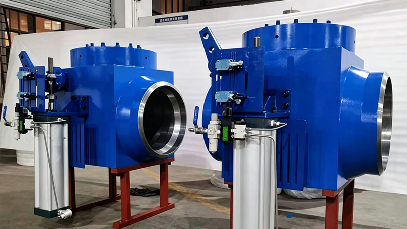
API 602 Gate Valve: Complete Guide to Features, Specifications, and Applications

📋 Key Takeaways

  • API 602 covers compact forged steel gate valves for refinery, chemical, and power plant services in sizes NPS 1/4 to 4.
  • Threaded, socket-weld, and flanged end connections accommodate diverse piping system requirements.
  • Reduced-port design provides significant weight and cost savings while meeting full pressure containment requirements.
  • Materials comply with ASTM standards and NACE MR0175 for sour gas service environments.

however, This complete API 602 gate valve guide covers aPI 602 is the American Petroleum Institute standard that covers compact, bolted bonnet, forged steel gate valves for petroleum and natural gas industry applications. These valves are designed for NPS 1/4″ through NPS 4″ (DN 8 to DN 100) and pressure classes from 150LB to 2500LB. API 602 gate valves are distinguished by their forged steel construction, which provides superior strength, pressure integrity, and resistance to shock loads compared to cast steel alternatives.

api 602 gate valve - API 602 forged steel gate valve - industrial gate valve

therefore, Unlike the larger API 600 cast steel gate valves, API 602 valves are manufactured through forging processes that align the metal grain structure with the valve body contours, resulting in higher mechanical strength and better resistance to pressure-induced stresses. This makes them the preferred choice for critical service applications where reliability and safety are paramount.

API 602 Gate Valve

Key Features of API 602 Gate Valves

1. Forged Steel Body Construction

furthermore, The defining characteristic of API 602 gate valves is their forged steel body. Forging eliminates internal voids, porosity, and inclusions that can occur in castings. The forging process produces a dense, uniform grain structure that delivers superior mechanical properties including higher tensile strength, improved impact resistance, and better fatigue life. Available body materials include A105 (carbon steel), F304/F316 (stainless steel), F11/F22 (alloy steel), and F51 (duplex stainless steel) to match service requirements.

2. Bolted Bonnet Design

additionally, API 602 requires a bolted bonnet connection, which provides several advantages over welded or threaded bonnet designs. The bolted bonnet allows for easy in-line inspection, maintenance, and repair without removing the valve from the pipeline. This is especially important in critical services where downtime must be minimized. The bonnet gasket creates a reliable seal that can be replaced during routine maintenance.

3. Rising Stem and OS&Y Configuration

API 602 gate valves feature an Outside Screw and Yoke (OS&Y) design with a rising stem. The threaded stem is located outside the valve body and bonnet, preventing thread contact with the process fluid. This design provides visual position indication — a raised stem indicates an open valve. The OS&Y configuration also reduces wear on stem threads and packing, extending valve service life.

4. Full Port or Reduced Port Options

API 602 gate valves are available in both full port (full bore) and reduced port configurations. Full port valves have an internal diameter matching the pipe bore, minimizing pressure drop and allowing pig passage in pipeline applications. Reduced port valves have a smaller bore diameter that offers economic advantages in non-critical services where some pressure drop is acceptable.

5. Flexible Wedge or Solid Wedge Disc

The closure element of an API 602 gate valve can be either a flexible wedge or solid wedge disc. Flexible wedge discs are designed to compensate for variations in seating geometry caused by thermal expansion or piping loads, making them ideal for high-temperature and high-pressure applications. Solid wedge discs provide a simpler, more robust design suitable for moderate service conditions.

6. Renewable Seat Rings

API 602 standard calls for renewable or replaceable seat rings. These seat rings can be replaced when worn or damaged, extending the overall service life of the valve. Seat rings are typically made from corrosion-resistant materials and can be hard-faced with Stellite or other wear-resistant alloys for severe service applications.

API 602 Gate Valve

Api 602 gate valve: API 602 Technical Specifications

ParameterSpecification
Size RangeNPS 1/4″ to 4″ (DN 8 to DN 100)
Pressure ClassesClass 150LB, 300LB, 600LB, 900LB, 1500LB, 2500LB
Temperature Range-29°C to 538°C (-20°F to 1000°F)
Body MaterialsA105, LF2, F304, F316, F11, F22, F51, F53
Trim Materials13Cr, 304, 316, Stellite Hardfaced (API Trim 1-12)
End ConnectionsThreaded (NPT/BSPT), Socket Weld, Butt Weld, Flanged (RF/RTJ)
Bonnet TypeBolted Bonnet (Standard), Pressure Seal Bonnet (High Pressure)
Design StandardsAPI 602, ASME B16.34, ASME B16.5, ASME B16.10, ASME B16.25
Testing StandardsAPI 598, ISO 5208
OperationHandwheel, Gearbox, Pneumatic, Electric Actuator

Applications of API 602 Gate Valves

Oil and Gas Upstream

In upstream oil and gas operations, API 602 gate valves are used in wellhead equipment, flow lines, gathering systems, and manifold piping. The forged steel construction provides the integrity needed for high-pressure wellhead services where blowout prevention and leak-tight shutoff are critical. Sour service (NACE MR0175) trim options make them suitable for H₂S-containing environments.

Refinery and Petrochemical

Refineries rely on API 602 gate valves for process piping, catalyst handling, utility systems, and product transfer. The compact size of these valves (compared to API 600 valves) allows their use in tight piping arrangements common in refinery units.

Natural Gas Processing

Gas processing plants use API 602 gate valves in dehydration units, amine treatment systems, compressor stations, and pipeline metering facilities. Low-temperature carbon steel (ASTM A350 LF2) versions are available for cryogenic gas processing applications.

Power Generation

In thermal power plants, API 602 gate valves are employed in boiler feedwater systems, steam extraction lines, cooling water circuits, and fuel handling systems. Alloy steel versions (F11, F22) handle the high temperatures of superheated steam service.

Chemical Processing

The chemical industry uses API 602 gate valves for handling corrosive chemicals, acids, and caustic solutions. Stainless steel (F304, F316) and duplex stainless steel (F51) body materials provide corrosion resistance for aggressive chemical environments.

Offshore and Marine

Offshore platforms demand the highest integrity from their valve components. API 602 gate valves with corrosion-resistant trim, NACE compliance, and extended bonnet designs are standard in offshore production facilities.

API 602 vs API 600: Key Differences

CharacteristicAPI 602 (Compact Forged)API 600 (Cast Steel)
Body ConstructionForged SteelCast Steel
Size RangeNPS 1/4″ – 4″NPS 2″ – 36″+
Pressure RatingUp to 2500LBUp to 2500LB
Impact ResistanceSuperiorGood
Typical ApplicationsHigh-pressure small boreLarge diameter main lines
Cost per UnitHigherLower

For a more detailed comparison, see our API 600 vs API 602 Gate Valve: Complete Specification Guide.

For a comprehensive comparison of valve types, see our Ball Valve Complete Guide covering floating, trunnion, and V-port ball valves.

API 602 Gate Valve

API 602 Gate Valve FAQ

What is the difference between API 602 and API 600 gate valves?

API 602 covers compact, forged steel gate valves in sizes NPS 1/4″ to 4″, while API 600 covers cast steel gate valves in sizes NPS 2″ to 36″ and larger. API 602 valves are forged, providing superior strength and impact resistance, making them ideal for high-pressure small-bore applications. API 600 valves are cast and better suited for larger diameter mainline piping. See our detailed API 600 vs API 602 comparison guide for complete specifications.

What materials are available for API 602 gate valves?

API 602 gate valves are available in a range of forged materials including A105 (carbon steel) for standard service, F304/F316 (stainless steel) for corrosive environments, F11/F22 (alloy steel) for high-temperature applications, and F51/F53 (duplex stainless steel) for sour gas and aggressive chemical services. Trim materials range from 13Cr to Stellite hard-faced options per API Trim specifications.

What is the maximum pressure rating for API 602 gate valves?

API 602 gate valves are available in pressure classes up to 2500LB (Class 2500), which provides a maximum working pressure of up to 6,250 psi (431 bar) at ambient temperature, depending on the body material. Standard pressure classes include 150LB, 300LB, 600LB, 900LB, 1500LB, and 2500LB.

Can API 602 gate valves be used for sour gas service?

Yes, API 602 gate valves can be supplied with NACE MR0175/ISO 15156 compliant materials for sour gas (H₂S-containing) service. This requires specific material selections including hardness-controlled carbon steel bodies, corrosion-resistant trim materials, and appropriate heat treatment. Sour service valves must be clearly specified at the time of ordering.

What end connections are available for API 602 gate valves?

API 602 gate valves are available with threaded ends (NPT or BSPT), socket weld ends, butt weld ends, and flanged ends (RF or RTJ facing). The choice of end connection depends on the piping specification, pressure class, and service requirements. Socket weld and threaded ends are common for smaller sizes, while flanged connections are standard for larger sizes within the API 602 range. All materials per ASTM International standards.

Need an API 602 gate valve for your project? Contact Vornet Valve today for expert technical assistance and competitive pricing on forged steel gate valves.

API 600 Globe Valve vs Gate Valve: Key Differences and How to Choose

📌 Quick Summary:

This guide compares API 600 gate valves and globe valves — their design differences, flow characteristics, pressure ratings, cost considerations, and application-specific recommendations for isolation and throttling service.

📋 Key Takeaways

  • API 600 gate valves provide straight-through flow with minimal pressure drop for isolation (on/off) service.
  • API 600 globe valves deliver superior throttling and flow regulation due to their Z-path or Y-pattern flow design.
  • Gate valves cost less but operate slower; globe valves are preferred for frequent regulation and tight shut-off needs.
  • Both follow Class 150-2500 pressure ratings and use cast carbon/alloy steel bodies with renewable seat rings.

When selecting valves for high-pressure, high-temperature industrial applications, two of the most commonly compared types are API 600 gate valves and API 600 globe valves. While both follow the same pressure class standard (API 600), they serve fundamentally different purposes: gate valves are designed for isolation (on/off service), while globe valves excel at throttling and flow regulation.

Api 600 globe valve vs gate valve: API 600 Gate Valve vs Globe Valve: Quick Comparison

FeatureAPI 600 Gate ValveAPI 600 Globe Valve
Primary FunctionIsolation (on/off)Throttling & flow regulation
Flow PathStraight-through (low drop)Z-path or Y-pattern
Pressure RatingsClass 150-2500Class 150-2500
Size RangeNPS 2-60NPS 1/2-24
Temperature Range-196C to 680C-196C to 680C
MaterialsCarbon steel, stainless, alloyCarbon steel, stainless, alloy
Operation SpeedMulti-turn (slow)Multi-turn (slow)
CostLowerHigher

API 600 Globe Valve vs Gate Valve

What Is an API 600 Gate Valve?

An API 600 gate valve uses a wedge-shaped or parallel gate that moves perpendicular to the flow path. When fully open, the gate retracts entirely into the bonnet, creating a straight-through flow path with minimal pressure drop.

API 600 Globe Valve vs Gate Valve

What Is an API 600 Globe Valve?

An API 600 globe valve uses a linear-moving disc that seats against a stationary ring. The flow path changes direction, making globe valves ideal for throttling and regulating flow.

Key Differences Explained

Flow Control: Isolation vs Throttling

The fundamental difference is purpose. A gate valve’s flat gate creates turbulence when partially open. A globe valve’s contoured disc handles throttling conditions. Never use a gate valve for flow regulation.

Pressure Drop

Gate valves have the lowest pressure drop when fully open. Globe valves have 3-5x higher pressure drop due to directional flow change.

Size Range

API 600 gate valves reach NPS 60. Globe valves typically cap at NPS 24.

Cost

Gate valves are 15-25% less expensive than globe valves of the same size and class.

When to Use Which

ApplicationRecommendedReason
Main pipeline isolationGate valveLowest pressure drop
Flow regulationGlobe valveDesigned for partial opening
Frequent operationGlobe valveGate seats wear faster
ESD/emergency shutdownGate valveReliable shut-off
Bypass linesGlobe valvePrecise flow control
Large piping (>24)Gate valveGlobe not commonly available

API 600 Globe Valve vs Gate Valve

Real-World Application Scenarios

Understanding the practical differences between API 600 gate valves and globe valves helps engineers make better procurement decisions. The following table shows typical industrial applications and which valve type is recommended:

ApplicationRecommended ValveReason
Pipeline main line isolationAPI 600 Gate ValveLow pressure drop, straight-through flow, infrequent operation
Boiler feedwater regulationAPI 600 Globe ValvePrecise flow control needed, throttling capability essential
Emergency shutdown (ESD) systemsAPI 600 Gate ValveFast positive isolation with tight shut-off
Bypass lines around control valvesAPI 600 Globe ValveManual throttling for maintenance bypass scenarios
Storage tank isolationAPI 600 Gate ValveNormally open or closed, no throttling required

For additional valve comparison guides, see our Gate Valve vs Ball Valve comparison and Safety Valve vs Relief Valve guide.

FAQ: API 600 Gate and Globe Valves

Can I use a gate valve for throttling?

No. Gate valves are for fully open or closed only. Partial opening erodes seating surfaces. Use a globe valve for throttling.

Which has better shut-off?

Both provide bubble-tight shut-off per API 598 testing. Globe valves often maintain seal integrity longer.

Are pressure ratings the same?

Yes. Both follow ASME B16.34 pressure-temperature ratings for their class.

Which is easier to maintain?

Globe valves are easier. The disc and seat are more accessible for lapping or replacement vs gate valves requiring bonnet removal.

How to Select Between API 600 Gate Valve and Globe Valve: Decision Framework

Choosing the wrong valve type for your application can lead to premature failure, higher operating costs, and unsafe conditions. Use this step-by-step decision framework to determine whether an API 600 gate valve or an API 600 globe valve is right for your specific application:

Decision FactorChoose Gate Valve If…Choose Globe Valve If…
Primary functionIsolation only (on/off)Flow regulation or throttling
Operation frequencyInfrequent (few cycles/month)Frequent (daily cycling)
Pressure drop toleranceMust be minimalModerate drop is acceptable
Pipeline sizeNPS 24 and aboveNPS 24 and below
Flow direction changeStraight line onlyDirection change OK
Budget priorityLower initial cost neededWilling to pay for regulation
Maintenance accessFull bonnet removal acceptableTop-entry maintenance preferred

For applications requiring precise flow control with frequent adjustment, always choose an API 600 globe valve. For mainline isolation with minimal pressure loss, choose an API 600 gate valve. See also our Gate Valve vs Ball Valve comparison for a broader perspective on isolation valves.

What is the cost difference between API 600 gate valves and globe valves?

API 600 globe valves typically cost 15-25% more than gate valves of the same size and pressure class. The price difference is due to the more complex internal geometry of globe valves (Z-path or Y-pattern) and the tighter machining tolerances required for throttling service. For Class 150-300 sizes NPS 2-12, expect a premium of $200-$2,000 depending on materials and trim specifications.

Can API 600 gate valves and globe valves be used for high-temperature applications above 500°C?

Yes, both API 600 gate valves and globe valves are suitable for high-temperature service up to 680°C (1256°F) when specified with appropriate materials. For temperatures exceeding 425°C, standard carbon steel bodies should be replaced with chromium-molybdenum alloy steel (ASTM A217 WC6 or WC9). The trim material should also be upgraded to Stellite-faced seats and 13% chrome stainless steel or Inconel for the disc/seat rings to maintain hardness and resist creep at elevated temperatures.

API 600 Globe Valve vs Gate Valve

Conclusion

Choose an API 600 gate valve for isolation with minimal pressure drop. Choose an API 600 globe valve for precise flow regulation. For assistance, contact Vornet Valve.

Related: Ball Valve Guide | API 600 Gate Valve

Need an API 600 Gate Valve or Globe Valve for Your System?

Vornet Valve supplies API 600 gate valves and globe valves in sizes NPS 1/2″ to 60″, Class 150 to 2500, in carbon steel, stainless steel, and alloy materials. Contact us for sizing and selection assistance.

Request a Quote →
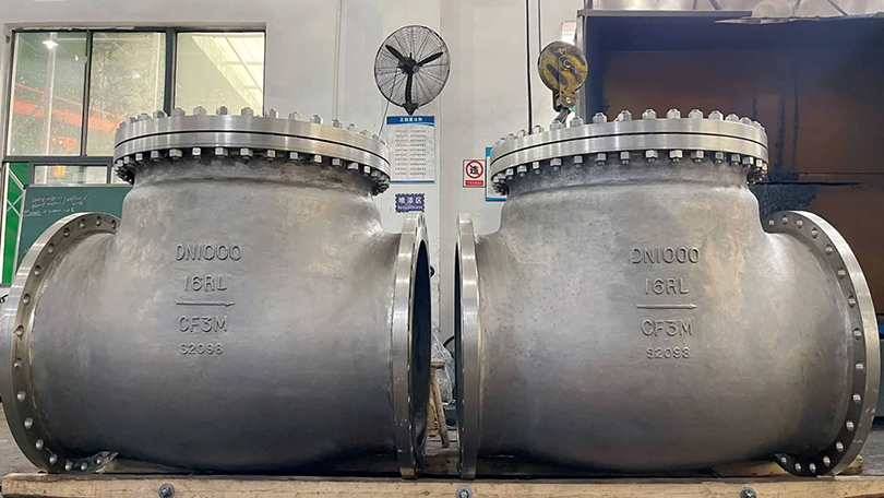
Trunnion vs Floating Ball Valve: Complete Selection Guide for Industrial Applications

📌 Quick Summary:

This guide compares floating vs trunnion ball valve designs across every parameter that affects total cost of ownership — bore size, pressure class, operating temperature, sealing mechanism, double block and bleed capability, and lifecycle cost. Includes a step-by-step selection framework for procurement engineers.

📋 Key Takeaways

  • Floating ball valves use line pressure to press the ball against the downstream seat, suitable for lower pressures and smaller sizes.
  • Trunnion-mounted ball valves support the ball with mechanical bearings, absorbing thrust for high-pressure and large-bore service.
  • Trunnion valves offer double-block-and-bleed capability, enabling positive isolation and maintenance safety.
  • Selection depends on pressure class, pipe size, operating temperature, and required shut-off class (API 6D).

Trunnion vs floating ball valve selection guide for industrial applications

This API 6D forged steel ball valve selection guide compares this API 6D forged steel ball valve comparison guide explains when to choose trunnion vs floating ball designs for high-pressure pipeline applications. After two decades of manufacturing ball valves for projects across six continents, one question comes up in nearly every technical review meeting: “Should we spec a floating or trunnion design for this application?” The answer is never a simple yes or no — it depends on bore size, pressure class, operating temperature, media characteristics, and the operational duty cycle. Making the wrong choice adds unnecessary cost at best, and at worst, creates a maintenance headache that compounds over the valve’s 20-to-30-year service life.

This guide walks through the engineering fundamentals, compares the two designs across every parameter that matters at the procurement level, and provides a decision framework you can apply directly to your next RFQ. It is written for procurement engineers, project managers, and valve distributors who need to specify correctly the first time — not after the first shutdown.

A floating ball valve gets its name from a simple design principle: the ball is not fixed to the valve body. Instead, it is suspended between two seat rings and held in place only by the stem at the top. When the valve is closed, upstream pressure pushes the ball against the downstream seat, creating the seal. The ball literally “floats” into position under media pressure.

This design has three defining characteristics that shape where it can and cannot be used:

1. Pressure-assisted sealing. The sealing force comes from the line pressure itself. Higher upstream pressure pushes the ball harder against the downstream seat. This works beautifully up to a point — but beyond that point, it becomes the design’s biggest liability. Once the force on the seat exceeds the seat material’s compressive limit, permanent deformation occurs and the valve begins to leak.

2. Stem-to-ball connection bears the full operating torque. Because the ball is not supported from below, 100% of the torque required to rotate the ball under pressure passes through the stem-to-ball slot connection. For small-bore valves at moderate pressures, this is manageable. For an NPS 12 valve at Class 600, the torque required quickly exceeds what a practical stem diameter can transmit without risk of stem twist or slot deformation.

3. Seat rings carry the full differential pressure load. In a floating design, the seats are structural elements, not just sealing elements. They must withstand the full force of the ball being driven into them by line pressure. This is why floating ball valves hit a hard ceiling around NPS 8 to NPS 10 in Class 150, and a much lower ceiling — around NPS 3 to NPS 4 — at Class 600 and above.

Floating ball valves remain the correct choice for small-to-medium bore, low-to-moderate pressure applications where simplicity and cost matter more than extreme durability. They dominate the NPS ½ through NPS 6 range in Class 150 and Class 300, which covers the majority of general industrial service — water, compressed air, light hydrocarbons, and non-critical chemical lines.

ParameterRange
Bore sizeNPS ½ – 10 (DN 15 – 250)
Pressure classClass 150 – 600 (occasionally 900 for small bores)
Temperature range-29°C to 200°C (standard PTFE seats); up to 300°C with reinforced PTFE
Body materialsCast carbon steel (WCB, LCB), cast stainless steel (CF8, CF8M), forged steel (A105, F316)
End connectionsFlanged (ASME B16.5), threaded (NPT), socket weld, butt weld
Design standardAPI 6D, ASME B16.34, API 608
Fire-safe availabilityYes — API 607 / API 6FA certified configurations available

What Is a Trunnion Ball Valve?

A trunnion ball valve solves the floating design’s fundamental limitation by mechanically fixing the ball in place. The ball has an integral shaft extension at both top and bottom — the upper trunnion connects to the stem, and the lower trunnion sits in a bearing in the valve body. The ball cannot move axially under pressure. Instead of the ball pushing into the seat, the seats are spring-loaded and press against the ball to create the seal.

This inversion of the sealing mechanism changes everything about how the valve performs at scale:

1. Sealing force is independent of line pressure. The spring-loaded seats provide a consistent, predictable sealing force regardless of whether the valve is handling 5 psi or 2,500 psi. This eliminates the seat deformation problem that limits floating designs. The seats are no longer structural — they are purely sealing components, which means they can be designed for optimal sealing geometry rather than compromising between sealing and load-bearing.

2. Operating torque stays low at any bore size. Because the ball is fully supported by upper and lower bearings, the stem only needs to overcome friction between the ball surface and the seats, plus bearing friction. A trunnion ball valve at NPS 24 and Class 600 can be operated by one person with a gearbox — the equivalent floating design would be physically impossible to open under pressure.

3. Double block and bleed capability is inherent. With spring-loaded seats on both sides, a trunnion ball valve naturally achieves upstream and downstream sealing simultaneously. When the cavity between seats is vented through the body bleed connection, the valve provides true double block and bleed (DBB) isolation — a critical safety requirement in oil and gas transmission pipelines.

4. The design scales to extreme sizes. Trunnion ball valves are manufactured up to NPS 60 and beyond, at pressure classes up to Class 2500. They are the standard choice for pipeline transmission, LNG terminals, refinery isolation, and any application where a leaking seat means a multi-million-dollar shutdown.

ParameterRange
Bore sizeNPS 2 – 60 (DN 50 – 1500)
Pressure classClass 150 – 2500
Temperature range-196°C (cryogenic) to 680°C (metal-seated, high-temp alloys)
Body materialsCarbon steel (A216 WCB, LCB, LCC), stainless steel (CF8M, CF3M), duplex (4A, 5A), alloy steels, Inconel 625 cladding, Monel, titanium
End connectionsFlanged (ASME B16.5, B16.47 Series A/B), butt weld (ASME B16.25), hub/clamp
Design standardAPI 6D, ASME B16.34, API 608, ISO 17292
Fire-safe certificationAPI 607, API 6FA, ISO 10497 — standard on most configurations

Trunnion vs Floating: The Engineering Comparison

Procurement decisions turn on more than just bore size and pressure. The table below compares the two designs across every parameter that affects total cost of ownership — not just the purchase price on the RFQ.

ParameterFloating Ball ValveTrunnion Ball Valve
Ball supportSuspended between seats; supported only by stemFixed by upper and lower trunnion bearings
Sealing mechanismLine pressure pushes ball into downstream seatSpring-loaded seats push against fixed ball
Sealing forceProportional to line pressure — increases with ΔPConstant — determined by spring design, independent of ΔP
Max practical boreNPS 10 (Class 150); NPS 4 (Class 600)NPS 60+ across all pressure classes
Max practical pressureClass 900 (NPS ≤3 only)Class 2500
Operating torqueHigh — increases sharply with bore and pressureLow and predictable — bearing friction dominates
Actuator sizingOversized actuator often required for safety marginCompact actuator possible — predictable torque curve
Seat lifeShorter — seats experience full ΔP compressive cyclingLonger — seats see controlled spring force only
Cavity overpressure protectionSelf-relieving seats required for liquid serviceSelf-relieving seats or external relief valve
Double block & bleedNot inherently availableStandard on most configurations
Relative cost (NPS 6, Class 300)Base: 1.0×1.5× to 2.5×
Relative cost (NPS 12, Class 600)N/A — typically not manufacturedBase: 1.0×
Maintenance complexityLow — few internal components; seats accessible from endsModerate — trunnion bearing inspection requires partial disassembly
Weight (NPS 8, Class 300)~120–180 kg~250–400 kg
Typical industriesGeneral industrial, water treatment, HVAC, light chemicalOil & gas transmission, refining, LNG, petrochemical, power generation, mining

Trunnion vs floating ball valve engineering comparison table

The cost comparison deserves a closer look because it is frequently misunderstood. A floating ball valve at NPS 6, Class 300 may cost half as much as its trunnion equivalent — but if it requires actuator upsizing, more frequent seat replacement, and eventual replacement after six to eight years instead of fifteen to twenty, the total cost of ownership can invert entirely. Procurement decisions should compare lifecycle costs, not RFQ line-item prices.

Trunnion Ball Valve Configurations and Their Applications

Not all trunnion ball valves are the same. The configuration — body style, seat material, and closure mechanism — determines which service conditions the valve can survive. Selecting the right configuration is as important as selecting trunnion over floating in the first place.

Fully Welded Trunnion Ball Valve

The body is constructed from forged steel sections welded together, with no body flanges or gaskets. This eliminates potential leak paths to atmosphere — a critical requirement for buried natural gas transmission pipelines where fugitive emissions regulations apply and excavation for repair costs more than the valve itself. Fully welded designs are the default choice for cross-country pipelines operating at Class 600 and above, and they dominate the NPS 12 through NPS 48 range in gas transmission service.

Application: Buried natural gas pipelines, crude oil transmission, refined product lines requiring zero atmospheric leakage.

Top-Entry Trunnion Ball Valve

The ball and seats are accessed by removing the bonnet from the top of the valve body, while the valve remains in-line. This is the configuration to specify when in-line maintenance capability is non-negotiable — particularly in refinery and process plant applications where taking a valve out of the pipeline for workshop repair means a unit shutdown. Top-entry designs cost more upfront than side-entry equivalents, but the savings from avoiding a single unplanned shutdown can recover the premium ten times over.

Application: Refinery isolation, chemical plant main process lines, any service where in-line maintenance is required.

Double Block and Bleed (DBB) Ball Valve

A DBB trunnion ball valve provides positive isolation on both upstream and downstream sides simultaneously, with a body cavity bleed that can be opened to verify zero leakage across either seat. This is the configuration required by most pipeline operator standards for positive isolation during maintenance activities, and it is increasingly specified in LNG, hydrogen, and other high-consequence services where a single-seat leak during maintenance could be catastrophic.

Application: Pipeline isolation, pig launcher/receiver isolation, LNG tank farm isolation, custody transfer metering stations.

Metal-Seated Trunnion Ball Valve

When the operating temperature exceeds what PTFE or reinforced polymer seats can withstand — or when the media contains abrasive solids that would destroy a soft seat in months — metal-to-metal seating becomes necessary. Tungsten carbide, Stellite, or chromium carbide coatings are applied to both the ball surface and the seat rings, typically via HVOF (High Velocity Oxygen Fuel) thermal spray. These valves can operate continuously at temperatures above 500°C and handle media such as fluid catalytic cracking (FCC) catalyst slurry, coal gasification syngas, and molten salt in concentrated solar power plants.

Application: High-temperature refinery services, catalyst handling, slurry pipelines, molten salt thermal storage, delayed coker switching service.

How to Choose: A Decision Framework

The following framework distills two decades of application engineering into a sequence of questions. Work through them in order — each answer narrows the field until the correct design is obvious.

Step 1: What is the bore size?

  • NPS 6 and below: Both floating and trunnion are technically viable. Continue to Step 2.
  • NPS 8 to NPS 10: Floating remains viable at Class 150–300. At Class 600, trunnion becomes the practical default.
  • NPS 12 and above: Trunnion is the only practical choice. Floating designs above NPS 12 exist in niche applications but are generally not recommended for industrial service.

Step 2: What is the pressure class?

  • Class 150–300: Floating ball valves are cost-effective up to NPS 10. Trunnion becomes preferable above NPS 8 if low operating torque or DBB capability is required.
  • Class 600: Floating is viable up to NPS 6 with appropriate actuator sizing. Above NPS 6, specify trunnion.
  • Class 900–1500: Trunnion across all bore sizes. Floating designs exist at very small bores (NPS 2 and below) but are not recommended for critical service.
  • Class 2500: Trunnion only — there is no floating design rated for Class 2500 in industrial practice.

Step 3: What is the operating temperature?

  • Below 200°C: Standard PTFE or Devlon seats are acceptable for both designs.
  • 200°C to 350°C: Reinforced PTFE or PEEK seats. Trunnion designs handle this range more reliably because seat loading is controlled rather than pressure-driven.
  • Above 350°C: Metal-seated trunnion ball valve is the only viable configuration. Floating designs with metal seats exist but have poor cycle life due to uncontrolled seating stress.
  • Cryogenic service (below -46°C): Extended-bonnet trunnion ball valve with cryogenic testing per BS 6364 or ISO 28921. Floating cryogenic designs exist for small bores (NPS 2 and below).

Step 4: What happens if this valve leaks?

This is the question that separates commodity procurement from engineered valve specification. If a leaking seat means a minor inconvenience — isolate the line at the next shutdown and replace the valve — a floating design is perfectly adequate. If a leaking seat means a plant shutdown, product loss, environmental release, or safety incident, the additional cost of a trunnion ball valve with DBB capability is an insurance policy that costs less than the deductible on a single incident.

Step 5: What is the duty cycle?

  • Infrequent operation (less than once per month): Floating ball valves are adequate. The higher operating torque is not a practical problem at low cycle rates.
  • Frequent operation (daily or weekly cycling): Trunnion is strongly preferred. Consistent low torque means the actuator lasts longer, and the controlled seat loading means the seats last longer — two factors that compound with cycle count.
  • throttling service will destroy the seats through wire drawing and cavitation within months.

Ball valve selection decision framework for procurement engineers

How to Choose the Best Trunnion Ball Valve for Your Application

Selecting the best trunnion ball valve depends on five key factors. The table below maps common operating conditions to the optimal trunnion configuration:

ApplicationRecommended Trunnion TypeSeat MaterialKey Feature
High-pressure gas transmission pipelineFully welded trunnionPTFE / Nylon with fire-safe backupZero external leakage, DBB, piggable full bore
Crude oil / refined product pipelineSide-entry or fully welded trunnionRPTFE / PEEKHigh-cycle life, replaceable seats, full bore
Refinery / petrochemical processTop-entry trunnionStellite 6 / Metal-seatedIn-line repairable, fire-safe, high-temp to 680°C
Cryogenic LNG / LPG serviceExtended stem trunnionPCTFE / PTFECold box installation, −196°C rating, fugitive emission
Subsea / offshore platformFully welded or side-entry trunnionPEEK / Metal-seatedROV-compatible, NACE MR0175, high-pressure
Power plant / steam serviceMetal-seated trunnionStellite / 316 overlayHigh-temp to 680°C, fire-safe, high cycle
Mining / abrasive slurryMetal-seated trunnionStellite / Tungsten carbideAbrasion-resistant trim, full bore for slurry flow

Procurement Considerations for B2B Buyers

Beyond the engineering selection, several procurement factors affect total cost of ownership and supply reliability — areas where the choice between floating and trunnion intersects with commercial strategy.

Lead Time Realities

Floating ball valves in standard materials (WCB/CF8M) and common size-pressure combinations are typically available from stock or with short lead times of two to four weeks. Trunnion ball valves above NPS 12, in alloy materials, or with special seat configurations (metal-seated, cryogenic) are almost always made to order with lead times of eight to sixteen weeks or longer. Procurement schedules must account for this.

Minimum Order Quantity and Bulk Pricing

For projects requiring multiple valves of the same specification — a common scenario in pipeline construction or refinery turnaround procurement — trunnion ball valves offer significant economies of scale. Manufacturers can batch-produce bodies and trim components, reducing unit cost. Floating ball valves, being higher-volume commodity items, already benefit from manufacturing scale at standard sizes, so the bulk discount curve is flatter.

Material Traceability

In oil and gas applications governed by API 6D, full material traceability per EN 10204 Type 3.1 or 3.2 is mandatory. This applies to both floating and trunnion designs, but trunnion valves with their larger number of pressure-containing components (trunnion, bearings, multiple seat rings) generate a correspondingly larger documentation package. Buyers should verify that their supplier can provide complete MTRs (Material Test Reports) for every pressure-containing and pressure-controlling component before placing an order.

Factory Acceptance Testing

Every trunnion ball valve above NPS 12 should undergo a factory acceptance test (FAT) that includes hydrostatic shell test, high-pressure and low-pressure seat tests per API 6D, and functional testing of the operator (manual gearbox or actuator). Specifying FAT requirements in the purchase order — rather than assuming they will be performed — is a hard-learned lesson from projects where valves arrived on site without documented test results.

When the Answer Is “It Depends”: Edge Cases Worth Knowing

Some applications fall into gray areas where the decision between floating and trunnion is not obvious. These cases come up often enough to deserve explicit discussion.

NPS 8, Class 300, clean gas service, operated twice per year. A floating ball valve will work and will cost less. A trunnion ball valve will also work, will cost more, and will provide DBB capability that this particular application does not require. Unless there is a compelling reason to spend more — a site-wide specification requiring DBB on all isolation valves, for example — the floating design is the correct commercial choice.

NPS 6, Class 600, hot oil at 320°C. This application is right on the boundary. A floating design with reinforced PTFE seats could work for a limited time, but the combination of temperature-driven seat degradation and pressure-driven seat loading creates a reliability risk. The engineering-preferred answer is a trunnion ball valve with PEEK seats or metal seats — the incremental cost buys a margin of safety that hot oil service demands.

NPS 3, Class 1500, instrument air isolation. Both designs exist in this size-pressure combination, and instrument air at ambient temperature is about as benign a service as exists. A floating ball valve will perform identically to a trunnion at a lower cost. Specify floating.

NPS 16, Class 600, crude oil pipeline with DBB requirement. There is no decision to make. Trunnion is the only design that exists at this size and pressure, and DBB capability is inherent. The question is which trunnion configuration — side-entry or top-entry, welded or flanged body — which moves the discussion into configuration selection rather than design-type selection.

Selection Checklist for Your Next RFQ

Before finalizing a ball valve specification, run through this checklist. Each “no” answer is a flag that warrants further engineering review.

  1. Bore size confirmed: Is the selected design rated for the required NPS at the specified pressure class?
  2. Pressure-temperature rating verified: Does the valve’s pressure-temperature curve per ASME B16.34 cover the maximum operating condition with appropriate margin?
  3. Seat material compatible: Will the seat material survive the minimum and maximum operating temperatures without degradation?
  4. Body material compatible with media: Is the body material resistant to corrosion, hydrogen embrittlement, or other media-driven degradation mechanisms?
  5. End connection standard confirmed: Are the flanges, weld ends, or hub connections compatible with the mating pipe specification?
  6. Actuator sized correctly: Does the actuator torque output exceed the valve’s maximum break torque under worst-case differential pressure by a minimum safety factor of 1.5×?
  7. Fire-safe certification required: If yes, is API 607 or API 6FA certification available for this configuration?
  8. DBB capability required: If yes, is the valve configured with double-piston-effect seats and a cavity bleed?
  9. Fugitive emissions compliance: Does the stem seal meet ISO 15848 or applicable local fugitive emissions standards?
  10. Documentation package defined: Are MTRs, test reports, and certification documents specified in the purchase order?

For buyers sourcing from a factory-direct manufacturer, request a pre-production technical data sheet that confirms all of the above points in writing before the order is released for production. This single step prevents more post-delivery disputes than any other quality-control measure.

At Vornet Valve, our engineering team provides detailed technical proposals for every trunnion and floating ball valve inquiry — including material selection rationale, seat design calculations, and actuator sizing recommendations — at no cost during the quotation stage. View our industrial ball valve range or contact our engineering team to discuss your specific application requirements.

For further reading, see our detailed guides on floating ball valve specifications, fully welded trunnion ball valves, and metal-seated trunnion configurations.

API 6D Compliance: What It Means for Your Ball Valve Selection

API 6D is the primary international standard for pipeline ball valves, covering design, manufacturing, testing, and documentation requirements for trunnion and floating ball valves used in oil & gas transmission, refining, and petrochemical service. When you search for “API 6D forged steel valve”, you are looking for a ball valve that meets the most rigorous quality and safety benchmark in the pipeline industry.

Key API 6D Requirements for Ball Valves

RequirementWhat It MeansWhy It Matters
Design StandardCompliant with ASME B16.34 pressure-temperature ratingEnsures safe operation at rated pressure
Shell Test1.5x rated pressure hydrostatic testValidates body & bonnet integrity
Seat Leakage TestClass VI (soft seat) or Class IV (metal seat) per API 598 / ISO 5208Verifies bubble-tight shut-off
Double Block & Bleed (DBB)Trunnion ball valve must demonstrate dual seat sealing with body cavity bleedCritical for isolation safety in pipeline maintenance
Fire-safe DesignAPI 607 fire test certification for soft-seated valvesMaintains sealing integrity during fire conditions
Material TraceabilityFull chemical & mechanical certification for pressure-containing partsRequired for NACE MR0175 sour service
Fugitive EmissionISO 15848-1 optional but increasingly specifiedMeets environmental regulations (TA-Luft)

API 6D Floating vs Trunnion Ball Valve

ParameterFloating (API 6D)Trunnion (API 6D)
Size RangeNPS 2″ — 12″ (DN 50 — 300)NPS 4″ — 60″ (DN 100 — 1500)
Pressure ClassClass 150 — 600Class 150 — 2500
Temperature−29°C to 200°C (soft seat)−196°C to 680°C (metal seat)
DBB CapabilityNot available (single downstream seal)Standard (dual independent seats)
Fire-safe (API 607)Available with fire-safe seat designStandard, even with soft seats
Best ForGeneral pipelines, chemical, waterHigh-pressure gas, crude oil, cryogenic LNG
Relative Cost~40% less than equivalent trunnionBaseline for critical service

confirmation documents before shipment.

API 6D ball valve compliance and procurement FAQ

>Frequently Asked Questions

Q1: What is the difference between floating and trunnion ball valve?

The fundamental difference is in how the ball is supported and how sealing force is generated. In a floating ball valve, the ball is suspended between two seats and pushed against the downstream seat by line pressure to create a seal. In a trunnion ball valve, the ball is mechanically fixed in place by upper and lower bearings, and spring-loaded seats press against the ball to create the seal. This structural difference determines the maximum practical bore size, pressure rating, operating torque, and service life of each design.

Q2: When should I use a trunnion ball valve instead of floating?

Specify a trunnion ball valve when any of the following conditions apply: bore size above NPS 10, pressure class above Class 600, operating temperature above 350°C requiring metal seats, double block and bleed isolation is required, the valve will be cycled frequently (weekly or more), or the application is in a high-consequence service where a leaking seat would cause a plant shutdown, environmental release, or safety incident. For small-bore, low-pressure, general industrial service, a floating ball valve is typically the correct commercial choice.

Q3: What size range can trunnion ball valves cover?

Trunnion ball valves are manufactured from NPS 2 (DN 50) up to NPS 60 (DN 1500) and beyond for specialized applications. The most common range in industrial procurement is NPS 6 through NPS 36, covering the majority of pipeline, refinery, and process plant isolation applications. Above NPS 48, valves are typically custom-engineered to project-specific requirements.

Are trunnion ball valves suitable for high-pressure applications?

Yes — trunnion ball valves are the standard choice for high-pressure applications from Class 600 through Class 2500. Because the ball is mechanically supported rather than pressure-loaded against the seats, the sealing mechanism remains reliable at pressures that would deform the seats in a floating design. For Class 2500 service, trunnion is the only practical ball valve configuration in industrial practice.

What materials are trunnion ball valves available in?

Standard body materials include cast carbon steel (ASTM A216 WCB, LCB, LCC), cast stainless steel (A351 CF8M, CF3M), duplex stainless steel (A995 4A, 5A), and forged steels (A105, A350 LF2, A182 F316). For corrosive or high-temperature service, alloy steels, Inconel 625 cladding, Hastelloy, Monel, and titanium are available. Seat materials range from PTFE and Devlon for standard service to PEEK for elevated temperatures and tungsten carbide or Stellite for metal-seated high-temperature or abrasive service.

Do floating ball valves have a size limit?

Yes. The practical upper limit for floating ball valves is approximately NPS 10 at Class 150, NPS 8 at Class 300, and NPS 4 at Class 600. Above these sizes, the force required to seal the ball against the seat under pressure becomes excessive, leading to unacceptably high operating torque and accelerated seat wear. Some manufacturers produce floating designs slightly above these limits for niche applications, but they are not recommended for general industrial service.

Can a floating ball valve provide double block and bleed?

Not inherently. A standard floating ball valve seals against the downstream seat only — the upstream seat is not pressure-energized in the same way. Some manufacturers offer floating designs with double-piston-effect seats that can achieve DBB, but this is uncommon and adds cost that often approaches trunnion pricing. For applications requiring verified DBB isolation, a trunnion ball valve is the industry-standard solution.

What is the typical service life difference between floating and trunnion designs?

In comparable service conditions, a trunnion ball valve typically achieves 1.5× to 3× the seat life of a floating equivalent because the spring-loaded seats experience controlled, consistent loading rather than the pressure-proportional loading of a floating design. However, service life is highly application-dependent — a floating ball valve in clean water service at ambient temperature may outlast a trunnion valve in abrasive slurry service by a factor of ten. The design choice is only one variable in the service life equation; media characteristics, duty cycle, and maintenance practices matter just as much.

Need a Ball Valve for Your Pipeline System?

Vornet Valve supplies floating and trunnion-mounted ball valves in sizes NPS 1/2″ to 60″, Class 150 to 2500, in carbon steel, stainless steel, duplex, and exotic alloys. Contact our engineering team for sizing and material selection assistance.

Request a Quote →