Trunnion vs Floating Ball Valve: Complete Selection Guide for Industrial Applications
After two decades of manufacturing ball valves for projects across six continents, one question comes up in nearly every technical review meeting: “Should we spec a floating or trunnion design for this application?” The answer is never a simple yes or no — it depends on bore size, pressure class, operating temperature, media characteristics, and the operational duty cycle. Making the wrong choice adds unnecessary cost at best, and at worst, creates a maintenance headache that compounds over the valve’s 20-to-30-year service life.
This guide walks through the engineering fundamentals, compares the two designs across every parameter that matters at the procurement level, and provides a decision framework you can apply directly to your next RFQ. It is written for procurement engineers, project managers, and valve distributors who need to specify correctly the first time — not after the first shutdown.
What Is a Floating Ball Valve?
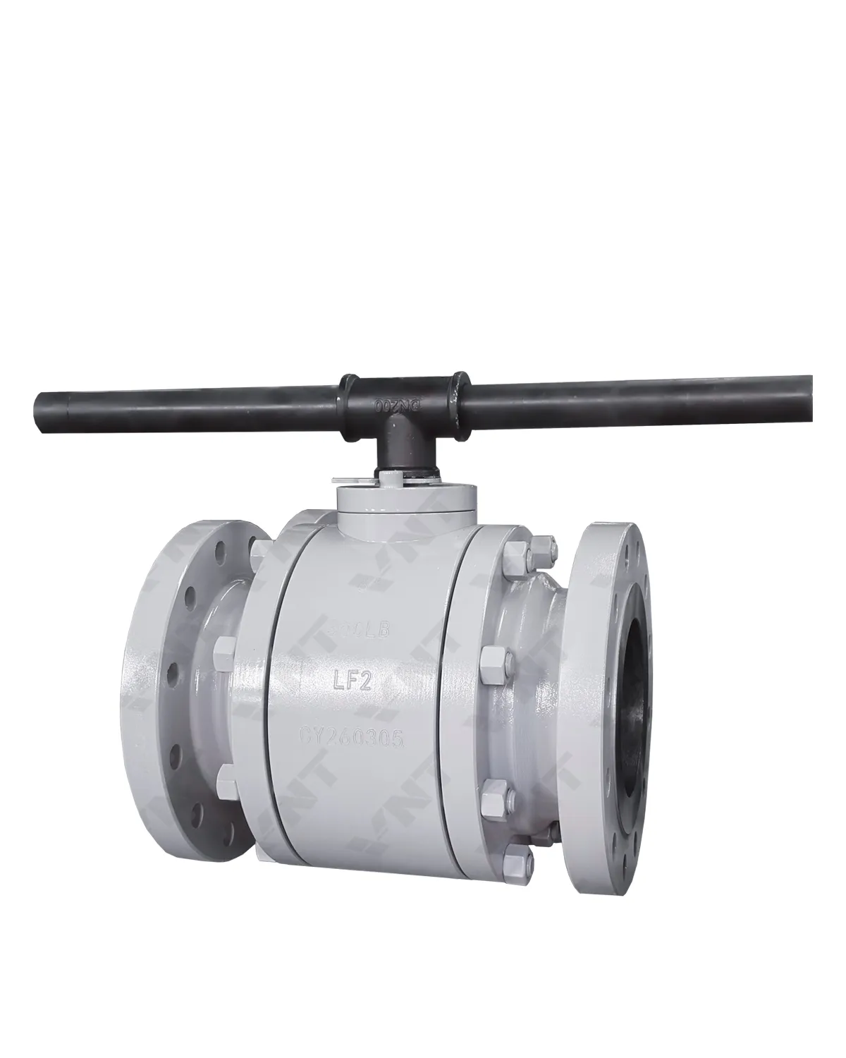
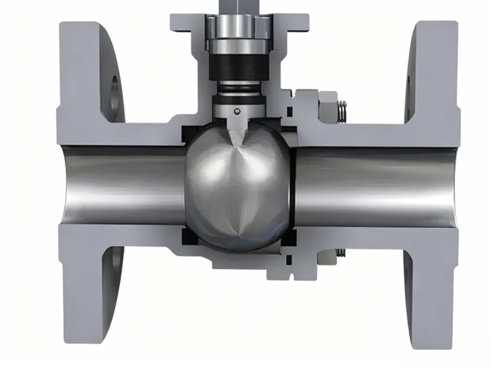
A floating ball valve gets its name from a simple design principle: the ball is not fixed to the valve body. Instead, it is suspended between two seat rings and held in place only by the stem at the top. When the valve is closed, upstream pressure pushes the ball against the downstream seat, creating the seal. The ball literally “floats” into position under media pressure.
This design has three defining characteristics that shape where it can and cannot be used:
1. Pressure-assisted sealing. The sealing force comes from the line pressure itself. Higher upstream pressure pushes the ball harder against the downstream seat. This works beautifully up to a point — but beyond that point, it becomes the design’s biggest liability. Once the force on the seat exceeds the seat material’s compressive limit, permanent deformation occurs and the valve begins to leak.
2. Stem-to-ball connection bears the full operating torque. Because the ball is not supported from below, 100% of the torque required to rotate the ball under pressure passes through the stem-to-ball slot connection. For small-bore valves at moderate pressures, this is manageable. For an NPS 12 valve at Class 600, the torque required quickly exceeds what a practical stem diameter can transmit without risk of stem twist or slot deformation.
3. Seat rings carry the full differential pressure load. In a floating design, the seats are structural elements, not just sealing elements. They must withstand the full force of the ball being driven into them by line pressure. This is why floating ball valves hit a hard ceiling around NPS 8 to NPS 10 in Class 150, and a much lower ceiling — around NPS 3 to NPS 4 — at Class 600 and above.
Floating ball valves remain the correct choice for small-to-medium bore, low-to-moderate pressure applications where simplicity and cost matter more than extreme durability. They dominate the NPS ½ through NPS 6 range in Class 150 and Class 300, which covers the majority of general industrial service — water, compressed air, light hydrocarbons, and non-critical chemical lines.
| Parameter | Range |
|---|---|
| Bore size | NPS ½ – 10 (DN 15 – 250) |
| Pressure class | Class 150 – 600 (occasionally 900 for small bores) |
| Temperature range | -29°C to 200°C (standard PTFE seats); up to 300°C with reinforced PTFE |
| Body materials | Cast carbon steel (WCB, LCB), cast stainless steel (CF8, CF8M), forged steel (A105, F316) |
| End connections | Flanged (ASME B16.5), threaded (NPT), socket weld, butt weld |
| Design standard | API 6D, ASME B16.34, API 608 |
| Fire-safe availability | Yes — API 607 / API 6FA certified configurations available |
What Is a Trunnion Ball Valve?
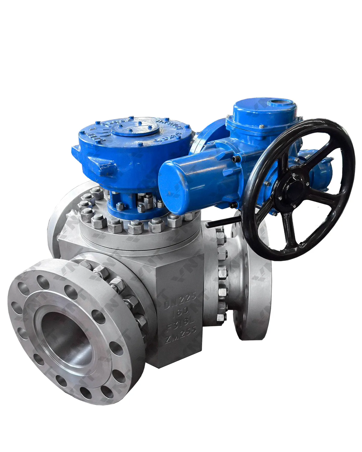
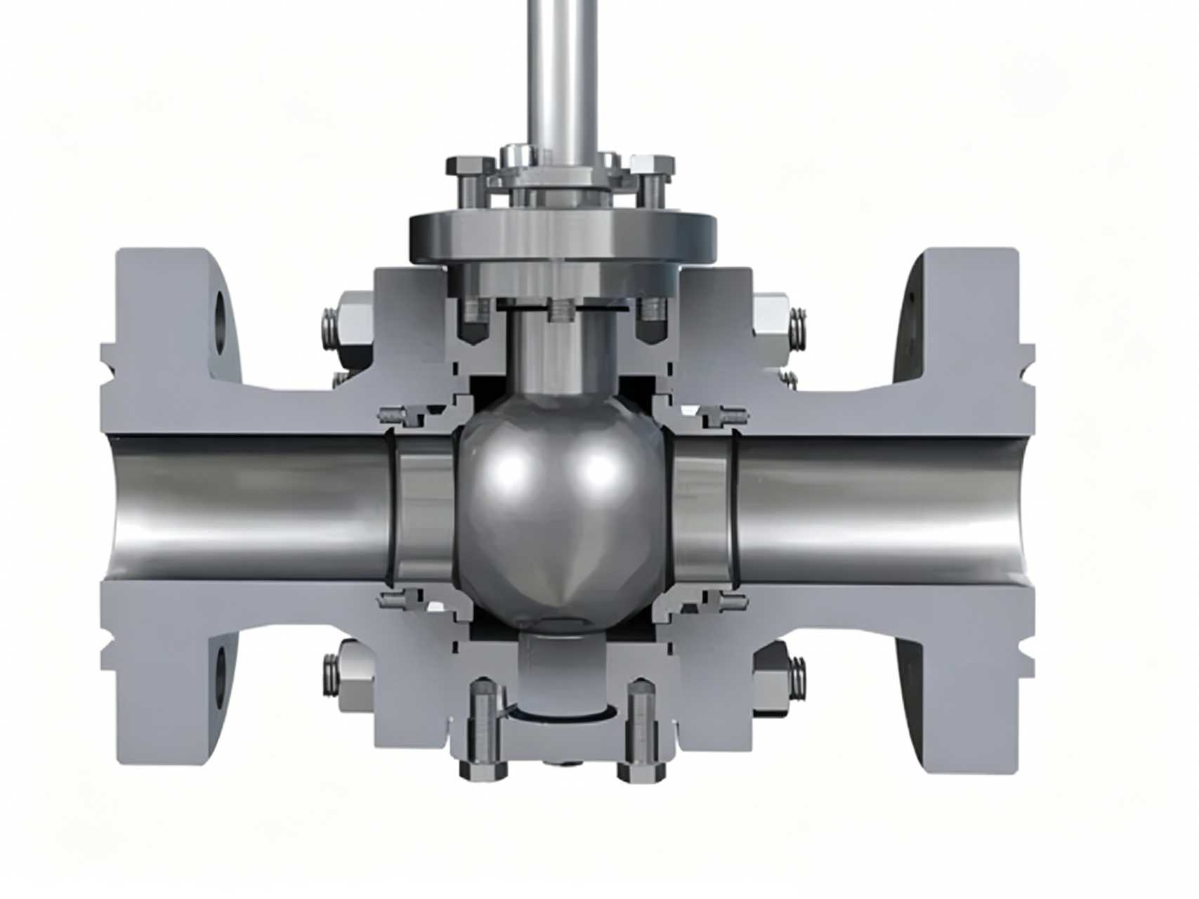
A trunnion ball valve solves the floating design’s fundamental limitation by mechanically fixing the ball in place. The ball has an integral shaft extension at both top and bottom — the upper trunnion connects to the stem, and the lower trunnion sits in a bearing in the valve body. The ball cannot move axially under pressure. Instead of the ball pushing into the seat, the seats are spring-loaded and press against the ball to create the seal.
This inversion of the sealing mechanism changes everything about how the valve performs at scale:
1. Sealing force is independent of line pressure. The spring-loaded seats provide a consistent, predictable sealing force regardless of whether the valve is handling 5 psi or 2,500 psi. This eliminates the seat deformation problem that limits floating designs. The seats are no longer structural — they are purely sealing components, which means they can be designed for optimal sealing geometry rather than compromising between sealing and load-bearing.
2. Operating torque stays low at any bore size. Because the ball is fully supported by upper and lower bearings, the stem only needs to overcome friction between the ball surface and the seats, plus bearing friction. A trunnion ball valve at NPS 24 and Class 600 can be operated by one person with a gearbox — the equivalent floating design would be physically impossible to open under pressure.
3. Double block and bleed capability is inherent. With spring-loaded seats on both sides, a trunnion ball valve naturally achieves upstream and downstream sealing simultaneously. When the cavity between seats is vented through the body bleed connection, the valve provides true double block and bleed (DBB) isolation — a critical safety requirement in oil and gas transmission pipelines.
4. The design scales to extreme sizes. Trunnion ball valves are manufactured up to NPS 60 and beyond, at pressure classes up to Class 2500. They are the standard choice for pipeline transmission, LNG terminals, refinery isolation, and any application where a leaking seat means a multi-million-dollar shutdown.
| Parameter | Range |
|---|---|
| Bore size | NPS 2 – 60 (DN 50 – 1500) |
| Pressure class | Class 150 – 2500 |
| Temperature range | -196°C (cryogenic) to 680°C (metal-seated, high-temp alloys) |
| Body materials | Carbon steel (A216 WCB, LCB, LCC), stainless steel (CF8M, CF3M), duplex (4A, 5A), alloy steels, Inconel 625 cladding, Monel, titanium |
| End connections | Flanged (ASME B16.5, B16.47 Series A/B), butt weld (ASME B16.25), hub/clamp |
| Design standard | API 6D, ASME B16.34, API 608, ISO 17292 |
| Fire-safe certification | API 607, API 6FA, ISO 10497 — standard on most configurations |
Trunnion vs Floating: The Engineering Comparison
Procurement decisions turn on more than just bore size and pressure. The table below compares the two designs across every parameter that affects total cost of ownership — not just the purchase price on the RFQ.
| Parameter | Floating Ball Valve | Trunnion Ball Valve |
|---|---|---|
| Ball support | Suspended between seats; supported only by stem | Fixed by upper and lower trunnion bearings |
| Sealing mechanism | Line pressure pushes ball into downstream seat | Spring-loaded seats push against fixed ball |
| Sealing force | Proportional to line pressure — increases with ΔP | Constant — determined by spring design, independent of ΔP |
| Max practical bore | NPS 10 (Class 150); NPS 4 (Class 600) | NPS 60+ across all pressure classes |
| Max practical pressure | Class 900 (NPS ≤3 only) | Class 2500 |
| Operating torque | High — increases sharply with bore and pressure | Low and predictable — bearing friction dominates |
| Actuator sizing | Oversized actuator often required for safety margin | Compact actuator possible — predictable torque curve |
| Seat life | Shorter — seats experience full ΔP compressive cycling | Longer — seats see controlled spring force only |
| Cavity overpressure protection | Self-relieving seats required for liquid service | Self-relieving seats or external relief valve |
| Double block & bleed | Not inherently available | Standard on most configurations |
| Relative cost (NPS 6, Class 300) | Base: 1.0× | 1.5× to 2.5× |
| Relative cost (NPS 12, Class 600) | N/A — typically not manufactured | Base: 1.0× |
| Maintenance complexity | Low — few internal components; seats accessible from ends | Moderate — trunnion bearing inspection requires partial disassembly |
| Weight (NPS 8, Class 300) | ~120–180 kg | ~250–400 kg |
| Typical industries | General industrial, water treatment, HVAC, light chemical | Oil & gas transmission, refining, LNG, petrochemical, power generation, mining |
The cost comparison deserves a closer look because it is frequently misunderstood. A floating ball valve at NPS 6, Class 300 may cost half as much as its trunnion equivalent — but if it requires actuator upsizing, more frequent seat replacement, and eventual replacement after six to eight years instead of fifteen to twenty, the total cost of ownership can invert entirely. Procurement decisions should compare lifecycle costs, not RFQ line-item prices.
Trunnion Ball Valve Configurations and Their Applications
Not all trunnion ball valves are the same. The configuration — body style, seat material, and closure mechanism — determines which service conditions the valve can survive. Selecting the right configuration is as important as selecting trunnion over floating in the first place.
Fully Welded Trunnion Ball Valve
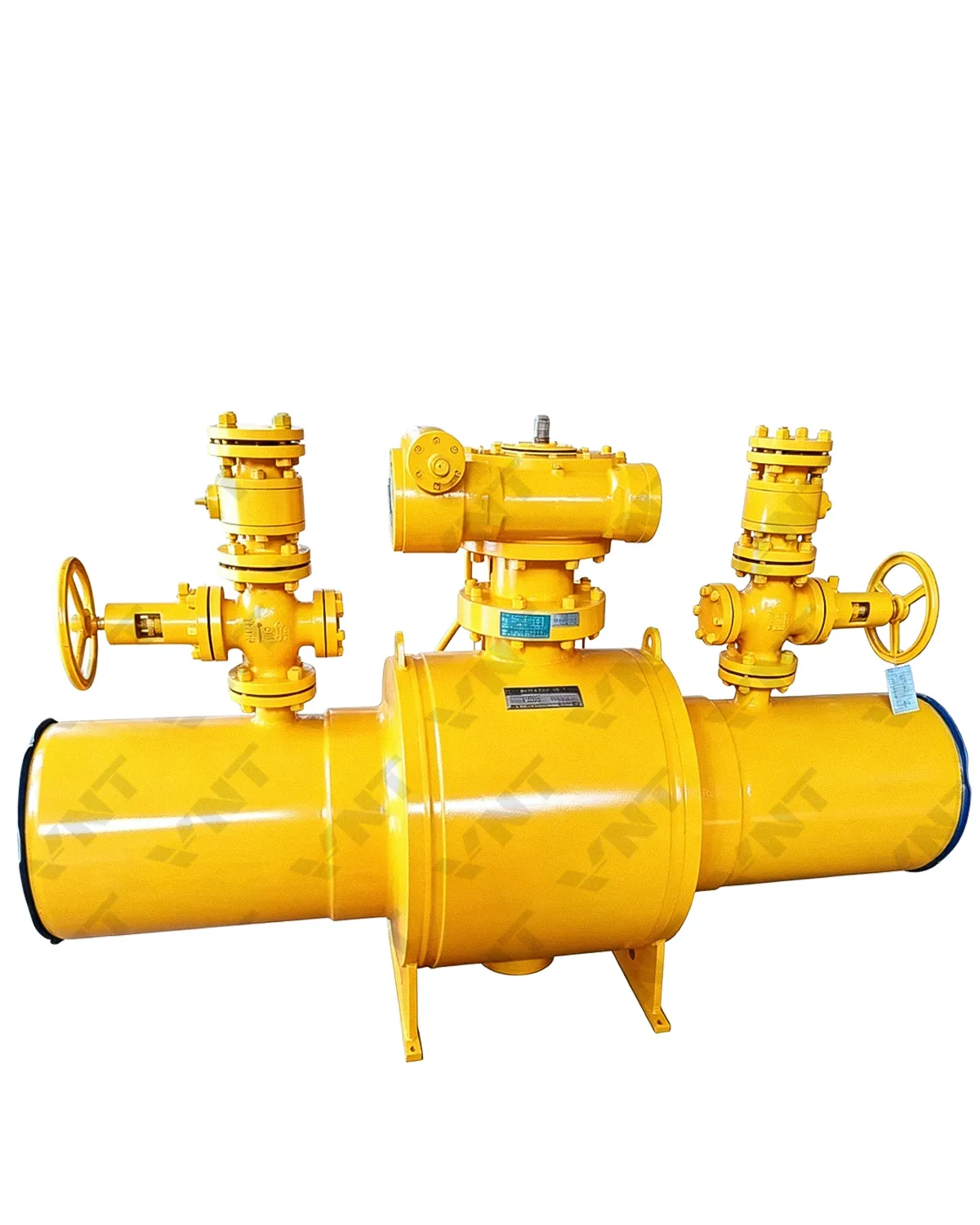
The body is constructed from forged steel sections welded together, with no body flanges or gaskets. This eliminates potential leak paths to atmosphere — a critical requirement for buried natural gas transmission pipelines where fugitive emissions regulations apply and excavation for repair costs more than the valve itself. Fully welded designs are the default choice for cross-country pipelines operating at Class 600 and above, and they dominate the NPS 12 through NPS 48 range in gas transmission service.
Application: Buried natural gas pipelines, crude oil transmission, refined product lines requiring zero atmospheric leakage.
Top-Entry Trunnion Ball Valve
The ball and seats are accessed by removing the bonnet from the top of the valve body, while the valve remains in-line. This is the configuration to specify when in-line maintenance capability is non-negotiable — particularly in refinery and process plant applications where taking a valve out of the pipeline for workshop repair means a unit shutdown. Top-entry designs cost more upfront than side-entry equivalents, but the savings from avoiding a single unplanned shutdown can recover the premium ten times over.
Application: Refinery isolation, chemical plant main process lines, any service where in-line maintenance is required.
Double Block and Bleed (DBB) Ball Valve
A DBB trunnion ball valve provides positive isolation on both upstream and downstream sides simultaneously, with a body cavity bleed that can be opened to verify zero leakage across either seat. This is the configuration required by most pipeline operator standards for positive isolation during maintenance activities, and it is increasingly specified in LNG, hydrogen, and other high-consequence services where a single-seat leak during maintenance could be catastrophic.
Application: Pipeline isolation, pig launcher/receiver isolation, LNG tank farm isolation, custody transfer metering stations.
Metal-Seated Trunnion Ball Valve
When the operating temperature exceeds what PTFE or reinforced polymer seats can withstand — or when the media contains abrasive solids that would destroy a soft seat in months — metal-to-metal seating becomes necessary. Tungsten carbide, Stellite, or chromium carbide coatings are applied to both the ball surface and the seat rings, typically via HVOF (High Velocity Oxygen Fuel) thermal spray. These valves can operate continuously at temperatures above 500°C and handle media such as fluid catalytic cracking (FCC) catalyst slurry, coal gasification syngas, and molten salt in concentrated solar power plants.
Application: High-temperature refinery services, catalyst handling, slurry pipelines, molten salt thermal storage, delayed coker switching service.
How to Choose: A Decision Framework
The following framework distills two decades of application engineering into a sequence of questions. Work through them in order — each answer narrows the field until the correct design is obvious.
Step 1: What is the bore size?
- NPS 6 and below: Both floating and trunnion are technically viable. Continue to Step 2.
- NPS 8 to NPS 10: Floating remains viable at Class 150–300. At Class 600, trunnion becomes the practical default.
- NPS 12 and above: Trunnion is the only practical choice. Floating designs above NPS 12 exist in niche applications but are generally not recommended for industrial service.
Step 2: What is the pressure class?
- Class 150–300: Floating ball valves are cost-effective up to NPS 10. Trunnion becomes preferable above NPS 8 if low operating torque or DBB capability is required.
- Class 600: Floating is viable up to NPS 6 with appropriate actuator sizing. Above NPS 6, specify trunnion.
- Class 900–1500: Trunnion across all bore sizes. Floating designs exist at very small bores (NPS 2 and below) but are not recommended for critical service.
- Class 2500: Trunnion only — there is no floating design rated for Class 2500 in industrial practice.
Step 3: What is the operating temperature?
- Below 200°C: Standard PTFE or Devlon seats are acceptable for both designs.
- 200°C to 350°C: Reinforced PTFE or PEEK seats. Trunnion designs handle this range more reliably because seat loading is controlled rather than pressure-driven.
- Above 350°C: Metal-seated trunnion ball valve is the only viable configuration. Floating designs with metal seats exist but have poor cycle life due to uncontrolled seating stress.
- Cryogenic service (below -46°C): Extended-bonnet trunnion ball valve with cryogenic testing per BS 6364 or ISO 28921. Floating cryogenic designs exist for small bores (NPS 2 and below).
Step 4: What happens if this valve leaks?
This is the question that separates commodity procurement from engineered valve specification. If a leaking seat means a minor inconvenience — isolate the line at the next shutdown and replace the valve — a floating design is perfectly adequate. If a leaking seat means a plant shutdown, product loss, environmental release, or safety incident, the additional cost of a trunnion ball valve with DBB capability is an insurance policy that costs less than the deductible on a single incident.
Step 5: What is the duty cycle?
- Infrequent operation (less than once per month): Floating ball valves are adequate. The higher operating torque is not a practical problem at low cycle rates.
- Frequent operation (daily or weekly cycling): Trunnion is strongly preferred. Consistent low torque means the actuator lasts longer, and the controlled seat loading means the seats last longer — two factors that compound with cycle count.
- Modulating or throttling service: Neither floating nor trunnion ball valves are designed for throttling. Specify a globe valve or characterized ball valve (V-port or segmented ball) for flow control applications. Using a standard ball valve for throttling will destroy the seats through wire drawing and cavitation within months.
How to Choose the Best Trunnion Ball Valve for Your Application
Selecting the best trunnion ball valve depends on five key factors. The table below maps common operating conditions to the optimal trunnion configuration:
| Application | Recommended Trunnion Type | Seat Material | Key Feature |
|---|---|---|---|
| High-pressure gas transmission pipeline | Fully welded trunnion | PTFE / Nylon with fire-safe backup | Zero external leakage, DBB, piggable full bore |
| Crude oil / refined product pipeline | Side-entry or fully welded trunnion | RPTFE / PEEK | High-cycle life, replaceable seats, full bore |
| Refinery / petrochemical process | Top-entry trunnion | Stellite 6 / Metal-seated | In-line repairable, fire-safe, high-temp to 680°C |
| Cryogenic LNG / LPG service | Extended stem trunnion | PCTFE / PTFE | Cold box installation, −196°C rating, fugitive emission |
| Subsea / offshore platform | Fully welded or side-entry trunnion | PEEK / Metal-seated | ROV-compatible, NACE MR0175, high-pressure |
| Power plant / steam service | Metal-seated trunnion | Stellite / 316 overlay | High-temp to 680°C, fire-safe, high cycle |
| Mining / abrasive slurry | Metal-seated trunnion | Stellite / Tungsten carbide | Abrasion-resistant trim, full bore for slurry flow |
Beyond the engineering selection, several procurement factors affect total cost of ownership and supply reliability — areas where the choice between floating and trunnion intersects with commercial strategy.
Lead Time Realities
Floating ball valves in standard materials (WCB/CF8M) and common size-pressure combinations are typically available from stock or with short lead times of two to four weeks. Trunnion ball valves above NPS 12, in alloy materials, or with special seat configurations (metal-seated, cryogenic) are almost always made to order with lead times of eight to sixteen weeks or longer. Procurement schedules must account for this.
Minimum Order Quantity and Bulk Pricing
For projects requiring multiple valves of the same specification — a common scenario in pipeline construction or refinery turnaround procurement — trunnion ball valves offer significant economies of scale. Manufacturers can batch-produce bodies and trim components, reducing unit cost. Floating ball valves, being higher-volume commodity items, already benefit from manufacturing scale at standard sizes, so the bulk discount curve is flatter.
Material Traceability
In oil and gas applications governed by API 6D, full material traceability per EN 10204 Type 3.1 or 3.2 is mandatory. This applies to both floating and trunnion designs, but trunnion valves with their larger number of pressure-containing components (trunnion, bearings, multiple seat rings) generate a correspondingly larger documentation package. Buyers should verify that their supplier can provide complete MTRs (Material Test Reports) for every pressure-containing and pressure-controlling component before placing an order.
Factory Acceptance Testing
Every trunnion ball valve above NPS 12 should undergo a factory acceptance test (FAT) that includes hydrostatic shell test, high-pressure and low-pressure seat tests per API 6D, and functional testing of the operator (manual gearbox or actuator). Specifying FAT requirements in the purchase order — rather than assuming they will be performed — is a hard-learned lesson from projects where valves arrived on site without documented test results.
When the Answer Is “It Depends”: Edge Cases Worth Knowing
Some applications fall into gray areas where the decision between floating and trunnion is not obvious. These cases come up often enough to deserve explicit discussion.
NPS 8, Class 300, clean gas service, operated twice per year. A floating ball valve will work and will cost less. A trunnion ball valve will also work, will cost more, and will provide DBB capability that this particular application does not require. Unless there is a compelling reason to spend more — a site-wide specification requiring DBB on all isolation valves, for example — the floating design is the correct commercial choice.
NPS 6, Class 600, hot oil at 320°C. This application is right on the boundary. A floating design with reinforced PTFE seats could work for a limited time, but the combination of temperature-driven seat degradation and pressure-driven seat loading creates a reliability risk. The engineering-preferred answer is a trunnion ball valve with PEEK seats or metal seats — the incremental cost buys a margin of safety that hot oil service demands.
NPS 3, Class 1500, instrument air isolation. Both designs exist in this size-pressure combination, and instrument air at ambient temperature is about as benign a service as exists. A floating ball valve will perform identically to a trunnion at a lower cost. Specify floating.
NPS 16, Class 600, crude oil pipeline with DBB requirement. There is no decision to make. Trunnion is the only design that exists at this size and pressure, and DBB capability is inherent. The question is which trunnion configuration — side-entry or top-entry, welded or flanged body — which moves the discussion into configuration selection rather than design-type selection.
Selection Checklist for Your Next RFQ
Before finalizing a ball valve specification, run through this checklist. Each “no” answer is a flag that warrants further engineering review.
- Bore size confirmed: Is the selected design rated for the required NPS at the specified pressure class?
- Pressure-temperature rating verified: Does the valve’s pressure-temperature curve per ASME B16.34 cover the maximum operating condition with appropriate margin?
- Seat material compatible: Will the seat material survive the minimum and maximum operating temperatures without degradation?
- Body material compatible with media: Is the body material resistant to corrosion, hydrogen embrittlement, or other media-driven degradation mechanisms?
- End connection standard confirmed: Are the flanges, weld ends, or hub connections compatible with the mating pipe specification?
- Actuator sized correctly: Does the actuator torque output exceed the valve’s maximum break torque under worst-case differential pressure by a minimum safety factor of 1.5×?
- Fire-safe certification required: If yes, is API 607 or API 6FA certification available for this configuration?
- DBB capability required: If yes, is the valve configured with double-piston-effect seats and a cavity bleed?
- Fugitive emissions compliance: Does the stem seal meet ISO 15848 or applicable local fugitive emissions standards?
- Documentation package defined: Are MTRs, test reports, and certification documents specified in the purchase order?
For buyers sourcing from a factory-direct manufacturer, request a pre-production technical data sheet that confirms all of the above points in writing before the order is released for production. This single step prevents more post-delivery disputes than any other quality-control measure.
At Vornet Valve, our engineering team provides detailed technical proposals for every trunnion and floating ball valve inquiry — including material selection rationale, seat design calculations, and actuator sizing recommendations — at no cost during the quotation stage. View our industrial ball valve range or contact our engineering team to discuss your specific application requirements.
For further reading, see our detailed guides on floating ball valve specifications, fully welded trunnion ball valves, and metal-seated trunnion configurations.
API 6D Compliance: What It Means for Your Ball Valve Selection
API 6D is the primary international standard for pipeline ball valves, covering design, manufacturing, testing, and documentation requirements for trunnion and floating ball valves used in oil & gas transmission, refining, and petrochemical service. When you search for “API 6D forged steel valve”, you are looking for a ball valve that meets the most rigorous quality and safety benchmark in the pipeline industry.
Key API 6D Requirements for Ball Valves
| Requirement | What It Means | Why It Matters |
|---|---|---|
| Design Standard | Compliant with ASME B16.34 pressure-temperature rating | Ensures safe operation at rated pressure |
| Shell Test | 1.5x rated pressure hydrostatic test | Validates body & bonnet integrity |
| Seat Leakage Test | Class VI (soft seat) or Class IV (metal seat) per API 598 / ISO 5208 | Verifies bubble-tight shut-off |
| Double Block & Bleed (DBB) | Trunnion ball valve must demonstrate dual seat sealing with body cavity bleed | Critical for isolation safety in pipeline maintenance |
| Fire-safe Design | API 607 fire test certification for soft-seated valves | Maintains sealing integrity during fire conditions |
| Material Traceability | Full chemical & mechanical certification for pressure-containing parts | Required for NACE MR0175 sour service |
| Fugitive Emission | ISO 15848-1 optional but increasingly specified | Meets environmental regulations (TA-Luft) |
API 6D Floating vs Trunnion Ball Valve
| Parameter | Floating (API 6D) | Trunnion (API 6D) |
|---|---|---|
| Size Range | NPS 2″ — 12″ (DN 50 — 300) | NPS 4″ — 60″ (DN 100 — 1500) |
| Pressure Class | Class 150 — 600 | Class 150 — 2500 |
| Temperature | −29°C to 200°C (soft seat) | −196°C to 680°C (metal seat) |
| DBB Capability | Not available (single downstream seal) | Standard (dual independent seats) |
| Fire-safe (API 607) | Available with fire-safe seat design | Standard, even with soft seats |
| Best For | General pipelines, chemical, water | High-pressure gas, crude oil, cryogenic LNG |
| Relative Cost | ~40% less than equivalent trunnion | Baseline for critical service |
For most API 6D pipeline applications above NPS 4″ or Class 600, a trunnion-mounted ball valve is the preferred choice. When specifying your next API 6D forged steel ball valve, confirm that the manufacturer provides full material traceability, shell & seat test reports, and fire-safe certification documents before shipment.
Frequently Asked QuestionsWhat is the difference between floating and trunnion ball valve?
The fundamental difference is in how the ball is supported and how sealing force is generated. In a floating ball valve, the ball is suspended between two seats and pushed against the downstream seat by line pressure to create a seal. In a trunnion ball valve, the ball is mechanically fixed in place by upper and lower bearings, and spring-loaded seats press against the ball to create the seal. This structural difference determines the maximum practical bore size, pressure rating, operating torque, and service life of each design.
When should I use a trunnion ball valve instead of floating?
Specify a trunnion ball valve when any of the following conditions apply: bore size above NPS 10, pressure class above Class 600, operating temperature above 350°C requiring metal seats, double block and bleed isolation is required, the valve will be cycled frequently (weekly or more), or the application is in a high-consequence service where a leaking seat would cause a plant shutdown, environmental release, or safety incident. For small-bore, low-pressure, general industrial service, a floating ball valve is typically the correct commercial choice.
What size range can trunnion ball valves cover?
Trunnion ball valves are manufactured from NPS 2 (DN 50) up to NPS 60 (DN 1500) and beyond for specialized applications. The most common range in industrial procurement is NPS 6 through NPS 36, covering the majority of pipeline, refinery, and process plant isolation applications. Above NPS 48, valves are typically custom-engineered to project-specific requirements.
Are trunnion ball valves suitable for high-pressure applications?
Yes — trunnion ball valves are the standard choice for high-pressure applications from Class 600 through Class 2500. Because the ball is mechanically supported rather than pressure-loaded against the seats, the sealing mechanism remains reliable at pressures that would deform the seats in a floating design. For Class 2500 service, trunnion is the only practical ball valve configuration in industrial practice.
What materials are trunnion ball valves available in?
Standard body materials include cast carbon steel (ASTM A216 WCB, LCB, LCC), cast stainless steel (A351 CF8M, CF3M), duplex stainless steel (A995 4A, 5A), and forged steels (A105, A350 LF2, A182 F316). For corrosive or high-temperature service, alloy steels, Inconel 625 cladding, Hastelloy, Monel, and titanium are available. Seat materials range from PTFE and Devlon for standard service to PEEK for elevated temperatures and tungsten carbide or Stellite for metal-seated high-temperature or abrasive service.
Do floating ball valves have a size limit?
Yes. The practical upper limit for floating ball valves is approximately NPS 10 at Class 150, NPS 8 at Class 300, and NPS 4 at Class 600. Above these sizes, the force required to seal the ball against the seat under pressure becomes excessive, leading to unacceptably high operating torque and accelerated seat wear. Some manufacturers produce floating designs slightly above these limits for niche applications, but they are not recommended for general industrial service.
Can a floating ball valve provide double block and bleed?
Not inherently. A standard floating ball valve seals against the downstream seat only — the upstream seat is not pressure-energized in the same way. Some manufacturers offer floating designs with double-piston-effect seats that can achieve DBB, but this is uncommon and adds cost that often approaches trunnion pricing. For applications requiring verified DBB isolation, a trunnion ball valve is the industry-standard solution.
What is the typical service life difference between floating and trunnion designs?
In comparable service conditions, a trunnion ball valve typically achieves 1.5× to 3× the seat life of a floating equivalent because the spring-loaded seats experience controlled, consistent loading rather than the pressure-proportional loading of a floating design. However, service life is highly application-dependent — a floating ball valve in clean water service at ambient temperature may outlast a trunnion valve in abrasive slurry service by a factor of ten. The design choice is only one variable in the service life equation; media characteristics, duty cycle, and maintenance practices matter just as much.
Floating vs Trunnion Ball Valve: Detailed Comparison
| Selection Factor | Floating Ball Valve | Trunnion Ball Valve |
|---|---|---|
| Ball Support | Ball floats against downstream seat | Fixed trunnion supports ball, seats are spring-loaded |
| Size Range | NPS 1/2″ — 12″ (DN 15 — 300) | NPS 4″ — 60″ (DN 100 — 1500) |
| Pressure Class | Class 150 — 600 (PN 10 — 100) | Class 150 — 2500 (PN 10 — 420) |
| Temperature Range | −29°C to 200°C (PTFE seats) | −196°C to 680°C (metal seats) |
| Operating Torque | Higher — seat compresses ball | Lower — spring-loaded seats reduce friction |
| Seat Leakage Class | Class V–VI (soft seat) | Class IV–VI (metal or soft seat) |
| Double Block & Bleed | Not available | Standard (API 6D requirement for DBB) |
| Fire-safe Design | Available (API 607, secondary metal seat) | Standard with metal seat backup |
| Fugitive Emissions | Available (ISO 15848) | Standard with live-loaded stem packing |
| Body Styles | Side-entry, top-entry | Side-entry, top-entry, fully welded, split-body |
| Maintenance | Replaceable seats and stem seals | Replaceable seats, trunnion bearings, stem |
| Relative Cost (Class 300, NPS 8″) | $ — Baseline | $$$ — ~30–60% higher |
| Best For | Chemical, HVAC, water, general industrial piping | Oil & gas pipelines, refineries, power plants, cryogenic, subsea |
As a rule of thumb: if your application exceeds NPS 12″ or Class 600, or requires DBB capability, a trunnion ball valve is the correct choice. For smaller, lower-pressure general service, a floating ball valve offers superior value.