Industrial Gate Valve Selection Guide: 7 Core Factors for B2B Pipeline Procurement
Gate valves are among the most fundamental and widely deployed isolation valves in industrial piping systems worldwide. As a critical linear-motion on/off valve, the gate valve provides full-bore unobstructed flow with minimal pressure drop when fully open, making it the preferred choice for mainline isolation, pigging operations, and high-capacity process pipelines. For B2B procurement professionals, EPC contractors, and plant maintenance teams, selecting the correct gate valve configuration directly determines system reliability, operational safety, and total lifecycle cost. This industrial gate valve selection guide systematically breaks down 7 core technical factors that drive gate valve procurement decisions across oil & gas, petrochemical, power generation, water treatment and marine industries.
Gate valves function by lifting a rectangular or wedge-shaped gate out of the flow path, providing a straight-through conduit with negligible turbulence. Unlike globe valves that throttle flow, gate valves are designed exclusively for full-open or full-closed service — partial opening causes gate vibration, seat erosion, and accelerated wear. Understanding this fundamental operational constraint is the first step toward proper gate valve sizing and material selection for industrial B2B pipeline projects.
1. Medium Property Analysis
1.1 Chemical Property — Corrosivity Determines Body Material
The chemical nature of the process medium is the single most critical factor determining gate valve body and trim material selection. Different corrosive environments demand specific metallurgical solutions:
- Carbon Steel (WCB/WCC): Suitable for non-corrosive or mildly corrosive services — water, steam, oil, natural gas, and neutral hydrocarbon fluids at moderate temperatures. The most economical choice for general industrial water and hydrocarbon mainline isolation.
- 304 Stainless Steel (CF8): Provides good oxidation and mildly acidic corrosion resistance. Suitable for food-grade, pharmaceutical, and atmospheric corrosive environments where chloride levels are low. Resists nitric acid and organic acid at ambient to moderate temperatures.
- 316 Stainless Steel (CF8M): Molybdenum-enhanced austenitic stainless steel offering superior pitting resistance in chloride-bearing environments. The standard choice for chemical processing, marine atmosphere, coastal installations, and mildly acidic chloride-containing streams.
- Duplex Stainless Steel (4A/5A): Combines high strength with excellent chloride stress corrosion cracking resistance. Ideal for seawater cooling, offshore platform firewater, and high-pressure corrosive gas production piping where both mechanical strength and corrosion resistance are required.
- Hastelloy C276: Premium nickel-chromium-molybdenum alloy for extreme corrosive service — hydrochloric acid, hot sulfuric acid, wet chlorine gas, and high-temperature mixed acid environments. Reserved for the most aggressive chemical process duty where standard stainless grades fail.
1.2 Physical State — Particle-Laden Media Need Special Designs
Process fluids containing suspended solids, catalyst particles, slurry, or crystallization-prone media present unique challenges for gate valves. Standard wedge gate designs trap particulates between the wedge and seat faces, preventing full closure and causing seat scoring. For particle-laden pipelines, the following design adaptations are essential:
- Specify parallel slide gate valves with floating seats that self-align and wipe clean during each stroke cycle
- Incorporate body cavity flushing ports to purge accumulated solids from the valve body dead space
- Select hard-faced seats with Stellite or tungsten carbide overlay for abrasion resistance
- Consider knife gate valves with bevelled gate edges that cut through settled solids and fiber-laden slurries for specialized applications
- For high-temperature catalyst-laden streams (FCCU, coker), specify guided-disc parallel gate designs with enlarged body cavities to prevent solid accumulation and gate jamming
2. Key Operating Condition Parameters
2.1 Working Pressure & Surge Pressure
Gate valve pressure class selection must account for both steady-state operating pressure and transient surge events. Industry-standard pressure ratings follow ASME B16.34 class designations:
- Class 150: Standard duty for water, low-pressure steam, and general utility services up to 19.6 bar at ambient temperature
- Class 300: Medium-pressure hydrocarbon, chemical process, and refinery transfer lines up to 51.1 bar
- Class 600: High-pressure production manifolds, wellhead isolation, and compressor station piping up to 102.1 bar
- Class 900 / 1500: High-integrity pressure isolation for deep-well production, supercritical steam, and high-pressure gas transmission
- Class 2500: Extreme pressure service for ultra-deep wells, HIPPS-protected segments, and supercritical power plant applications
For liquid pipelines subject to water hammer, the selected gate valve pressure class must exceed the maximum surge pressure by a minimum factor of 1.1 to prevent body joint leakage and seat deformation. Gas pipeline blowdown and emergency shutdown (ESD) surge scenarios must also be evaluated.
2.2 Operating Temperature & Extreme Temperature
Temperature extremes fundamentally alter material mechanical properties, seal integrity, and operational torque requirements. Gate valve material selection must align with the full operating temperature envelope:
- Cryogenic Service (-196°C to -29°C): Extended bonnet designs with stainless steel body/bonnet in CF8M or CF3M. The extended bonnet moves the stem packing away from the cold zone to maintain seal integrity. LNG, liquid oxygen, and liquid nitrogen gate valves require degreased, moisture-free assembly and cryogenic type-testing per BS 6364.
- Low Temperature (-29°C to 0°C): Low Carbon Steel (LCC) or 3.5% Nickel steel body per ASME B16.34 low-temperature requirements. Impact-tested materials per ASME SA-352 ensure ductile fracture behavior below the nil-ductility transition temperature.
- Moderate Temperature (0°C to 425°C): Standard carbon steel WCB bodies with graphite-based flexible graphite stem packing and spiral-wound gaskets. This covers the majority of refinery, petrochemical and power plant gate valve applications.
- High Temperature (425°C to 570°C): Chrome-molybdenum alloy steel bodies (WC6, WC9, C5, C12) with Stellite-hardfaced seat rings and gate guide rails. Required for superheated steam, hot oil, and high-temperature hydrocarbon services.
- Extreme Temperature (>570°C): Austenitic stainless steel or nickel-alloy bodies with full hard-facing of all sliding contact surfaces. Reserved for refinery fired heater isolation, FCCU regenerator slide valve service, and supercritical boiler applications.
Temperature de-rating per ASME B16.34 pressure-temperature tables must be strictly applied — a Class 300 carbon steel gate valve rated at 51.1 bar at 38°C may only be rated for 25.9 bar at 425°C.
2.3 Pipeline Flow Rate & Nominal Diameter
Gate valves are inherently full-bore designs; the seat bore diameter matches the pipe internal diameter to minimize pressure drop and enable pigging. When sizing gate valves for process pipelines:
- The valve DN (nominal diameter) should match the connecting pipe nominal diameter for mainline block valve service
- For high-velocity gas pipelines (>30 m/s), verify that the gate at full-open position is clear of the flow stream to prevent flow-induced gate vibration
- For liquid pipelines with flow velocity exceeding 5 m/s, verify that the gate seating forces overcome hydrodynamic lifting forces
- Large-diameter gate valves (DN600 and above) typically require gear operators or powered actuation due to gate mass and seating/unseating thrust requirements
- For low-flow or metering bypass applications, reduced-bore or venturi-pattern gate valves offer weight and cost savings while maintaining block valve functionality
3. Gate Valve Structural Type Classification
The internal gate and seat configuration defines how the valve achieves positive shutoff and is the primary determinant of service suitability across temperature ranges, pressure classes, and media conditions.
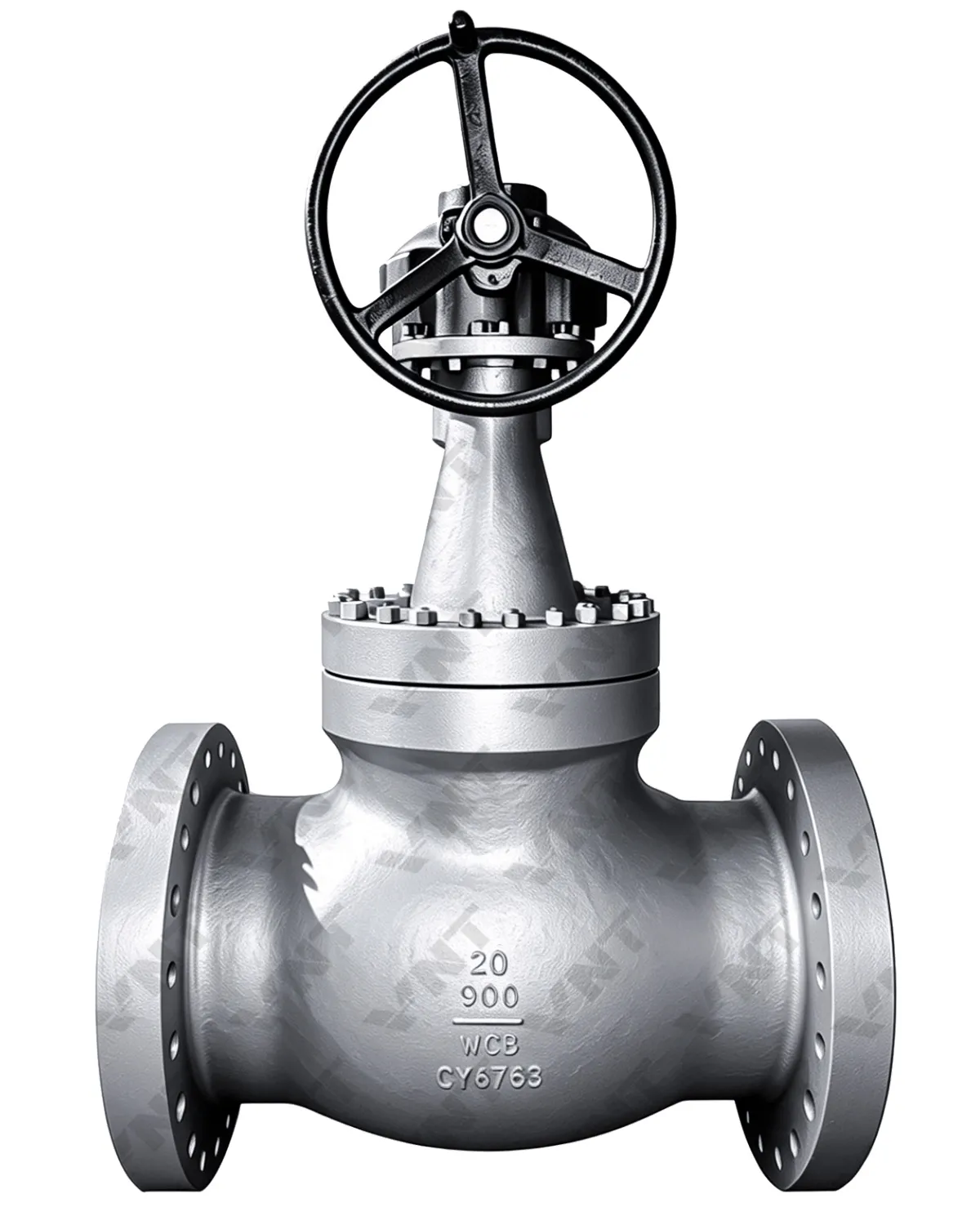
3.1 Wedge Gate Valve
The wedge gate valve features a single wedge-shaped gate that seats against matching tapered body seats. Wedge tightening action creates high seating stress for positive metal-to-metal shutoff. Two sub-types serve different temperature ranges:
- Flexible Wedge (-29°C to 425°C): The gate incorporates a machined peripheral groove or slot that allows the wedge faces to flex independently and self-align with the body seats during closure. This flexibility compensates for minor thermal misalignment and seat wear, maintaining leak-tight sealing in moderate-temperature thermal cycling services. The flexible wedge design tolerates body distortion from pipeline stress better than solid wedge variants, making it the preferred choice for above-ground piping subject to ambient temperature swings.
- Solid Single Wedge (-29°C to 570°C): A one-piece rigid wedge without any flexibility provision. The solid construction provides maximum mechanical integrity and resistance to flow-induced vibration at elevated temperatures. However, the rigid wedge is susceptible to thermal binding — if the valve is closed hot and allowed to cool, differential contraction between the wedge and body seats can lock the gate in the closed position. Solid wedge gate valves are therefore best specified for services where the valve remains in one position for extended periods (normally open block valves) or where operating temperature is constant.
3.2 Wedge Double Gate Valve (-29°C to 570°C)
The wedge double gate (or split-wedge) design employs two separate gate discs with a central spreading mechanism — typically a ball-and-socket or conical spreader between the discs. As the stem pushes downward, the spreader forces both discs outward against their respective body seats, creating independent seating force on each side. This configuration offers distinct advantages:
- Both gate faces seat independently, compensating for manufacturing tolerances and differential thermal expansion between the upstream and downstream sides
- The floating disc design eliminates thermal binding risk — even if thermal contraction occurs, the discs are not mechanically locked to the seats
- Double-disc construction maintains excellent sealing integrity under bi-directional pressure, making it suitable for block-and-bleed isolation where pressure may come from either direction
- Commonly used in high-temperature refinery services (coker, visbreaker, hydrocracker feed lines) up to 570°C
3.3 Parallel Gate Valve
Parallel gate valves employ a flat gate with parallel seating faces, using either a spring-energized spreading mechanism or line pressure to achieve downstream sealing. Two configurations cover different service ranges:
- Parallel Single Gate (-29°C to 350°C): A single flat gate disc positioned between parallel body seats, relying on downstream line pressure pushing the gate against the downstream seat for positive shutoff. The upstream seat experiences reduced sealing force at low differential pressures — this design is therefore oriented specifically with the pressure direction marked on the body. Parallel single gate valves excel in high-cycle isolation duties (tank farm manifold valves, loading rack isolation) where rapid open/close operation and minimal seat wear are required.
- Parallel Double Gate (-29°C to 570°C): Two independent gate discs with an internal spring or mechanical spreading mechanism that energizes both discs against their respective seats regardless of line pressure direction. This design provides true bi-directional tight shutoff and eliminates the orientation sensitivity of single-disc parallel gates. Parallel double gate valves are the standard choice for mainline block valves in gas transmission pipelines, refinery process unit isolation, and power plant steam header isolation where reliable bi-directional sealing at elevated temperatures is mandatory.
4. Actuation Mode
Gate valve actuation selection is driven by valve size, operating frequency, accessibility, safety requirements, and automation philosophy:
- Manual Handwheel: The most economical and reliable actuation method for gate valves up to DN300 in accessible locations with infrequent operation. Rising stem (OS&Y) handwheel-operated gate valves provide visual stem position indication — an important safety feature for field operators. For valves DN350 and above, a bevel gear operator reduces handwheel rim pull forces to practical limits. Manual gate valves remain the backbone of refinery unit block valve isolation where valves are operated only during turnaround maintenance.
- Electric Actuator: Multi-turn electric actuators provide remote operation capability with precise position feedback, torque monitoring, and programmable stroke limits. Essential for valves in hazardous or inaccessible locations — tank roof isolation, buried valve pits, high-elevation pipe racks, and process areas requiring operator evacuation during emergencies. Modern intelligent electric actuators support Modbus, Foundation Fieldbus, and HART communication protocols for integration into plant DCS and asset management systems. Electric actuation is also mandatory for emergency shutdown (ESD) gate valves requiring fail-in-place or fail-close functionality with SIL-rated safety integrity.
- Pneumatic Actuator: Pneumatic piston or scotch-yoke actuators deliver rapid stroke times (typically 3–15 seconds for full travel) for safety-critical isolation. Pneumatic gate valves are specified where fast emergency closure is required, where electrical power is unreliable, or where explosive atmospheres make electric actuation costly due to explosion-proof certification requirements. Spring-return pneumatic actuators achieve fail-safe close or fail-safe open functionality through stored spring energy without any external power source. Common in offshore platform firewater deluge systems, refinery ESD block valves, and gas processing plant emergency isolation.
5. Pipeline Connection Types
Gate valve end connections must match the piping specification while ensuring mechanical integrity under pressure, temperature, and external loads:
- Flanged Connection: The universal standard for industrial gate valves from DN15 through DN3000. ASME B16.5 raised face (RF) flanges provide positive gasket sealing with bolted joint integrity. For higher integrity, RTJ (ring-type joint) flanges with octagonal metal ring gaskets are specified for Class 900 and above, high-temperature hydrogen service, and cyclic pressure/fatigue duty. Flanged gate valves allow straightforward removal for maintenance without cutting pipe — essential for refinery and chemical plant installations where process unit turnaround windows are critical.
- Threaded Connection (NPT/Female): Cost-effective for small-bore gate valves (typically DN15–DN50, Class 800 and below) in utility services — instrument air, sampling lines, chemical injection quills, and drain/vent connections. Threaded gate valves eliminate welding costs but are limited to non-critical, low-vibration services where threaded joint leakage risk is acceptable.
- Welded Connection: Butt-weld (BW) end gate valves provide a permanent, leak-free connection for high-integrity pipelines where zero fugitive emissions are mandatory. Socket-weld (SW) ends serve small-bore high-pressure lines. Butt-weld gate valves are the industry standard for gas transmission pipelines, supercritical steam lines, high-pressure hydrogen service, and any application where flanged joint leakage or gasket degradation is unacceptable over the design life. Welded gate valves require field cutting for removal, so their use is reserved for permanent mainline installations with design lives of 25+ years.
6. Industrial Standards & Qualification
Gate valve design, manufacture, and testing must comply with internationally recognized standards that define material requirements, pressure-temperature ratings, dimensional interfaces, and quality assurance protocols:
- API 600 — Steel Gate Valves: The primary standard governing bolted bonnet steel gate valves for refinery, petrochemical, and natural gas industries. API 600 defines body/bonnet wall thickness, gate/seat design requirements, stem diameter minima, packing dimensions, and pressure-temperature ratings. Valves stamped with the API 600 monogram have been manufactured by an API-licensed facility under API Q1 quality management system oversight.
- API 602 — Compact Steel Gate Valves: Governs small-bore (DN50 and smaller) gate valves with threaded, socket-weld, or flanged ends for refinery and chemical plant services. API 602 gate valves feature compact body designs optimized for high-pressure small-bore isolation in tight piping configurations.
- ASME B31.1 — Power Piping: Defines the design, materials, fabrication, erection, and testing requirements for gate valves installed in power plant boiler external piping, steam distribution, and balance-of-plant piping systems. Gate valves specified for power generation must bear ASME B31.1-compliant material certifications and pressure-temperature ratings.
- ISO 5208 — Industrial Valves Pressure Testing: The international standard for shell strength and seat leakage acceptance criteria during production pressure testing. ISO 5208 defines leakage rate classes (Rate A through Rate D) for both metal-seated and soft-seated gate valves. Procurement specifications shall reference the required ISO 5208 seat tightness class — typically Rate B or better for critical isolation gate valves.
Beyond published standards, B2B procurement teams should verify gate valve manufacturer qualifications through documented fire-safe type testing records, fugitive emissions certification per ISO 15848-1, and positive material identification (PMI) reports for alloy body and trim materials. Manufacturers with in-house NDE capability (RT, UT, PT, MT per ASME Section V) and witnessed hydrostatic shell/seat testing provide the highest confidence in delivered valve quality.
Conclusion
Gate valve selection for industrial B2B pipeline procurement is a multi-dimensional engineering decision encompassing medium chemistry, pressure-temperature envelope, structural type, actuation philosophy, and connection specification. The systematic 7-factor evaluation framework presented in this guide — medium property analysis, operating conditions, gate structural type, actuation mode, connection type, and industry standards compliance — provides procurement professionals and project engineers with a structured methodology for gate valve technical specification.
The optimal gate valve selection balances technical performance requirements against total lifecycle cost. An API 600 carbon steel flexible-wedge flanged gate valve with manual handwheel operation may be the correct choice for an ambient-temperature water mainline isolation valve, while the same size line in high-pressure hydrogen service at 450°C demands a WC9 solid-wedge gate valve with butt-weld ends, Stellite hard-facing, and electric actuation with SIL-2 ESD functionality. Applying the seven core factors systematically ensures that each gate valve procurement decision serves the required process duty safely, reliably, and cost-effectively over the full asset lifecycle.
Gate Valve Class 600: Complete Selection Guide
Class 600 gate valves are among the most commonly specified pressure classes for industrial applications, balancing high-pressure capability with cost-effective design. This section provides a dedicated selection framework for Class 600 gate valves across different service conditions.
Class 600 Gate Valve Specifications at a Glance
| Specification | Class 600 Gate Valve |
|---|---|
| Pressure Rating | 1,480 PSI @ 100°F (10.2 MPa) — ASME B16.34 |
| Size Range | NPS 2″ — 36″ (DN 50 — 900) |
| Body Materials | WCB (A216), WC6 (A217), WC9 (A217), LCB (A352), CF8M (A351) |
| End Connections | Flanged (ASME B16.5), Butt-Weld (ASME B16.25) |
| Standards | API 600 (cast steel), API 602 (forged, ≤NPS 2″), ASME B16.34 |
| Trim Options | 13Cr, 304/316 SS, Stellite hardfaced seat & wedge |
| Bonnet Type | Bolted bonnet (standard), Pressure-seal (high-temp >400°C) |
| Operation | Handwheel, gearbox, pneumatic, electric actuator |
Class 600 Gate Valve Selection by Service
| Service Condition | Recommended Body | Trim | Pressure-Temp Rating |
|---|---|---|---|
| Water & general purpose | WCB (A216) | 13Cr / F6a | 1,480 PSI @ 100°F / 785 PSI @ 500°F |
| Steam up to 500°C | WC6 (1¼Cr-½Mo) | 13Cr + Stellite seat | 1,480 PSI @ 100°F / 570 PSI @ 900°F |
| Hydrocarbon / oil | WCB or LCB (A352) | 13Cr / Monel overlay | Per ASME B16.34 Class 600 |
| Sour gas (NACE) | LCB / LF2 | 316L / Inconel 625 overlay | Per NACE MR0175 limitations |
| High-temp steam >500°C | WC9 (2¼Cr-1Mo) | Stellite 6 full hardface | 1,480 PSI @ 100°F / 450 PSI @ 1,050°F |
| Cryogenic (−46°C) | LCB (A352) | 316L SS | Per ASME B16.34 at −46°C |
Class 600 is the most common gate valve pressure class in refining, petrochemical, and power generation applications. When specifying, confirm the body material grade (WCB for standard, WC6/WC9 for high-temp) and ensure the trim material meets your media compatibility requirements. Flexible wedge gate valves are recommended for Class 600 high-temperature service to prevent thermal binding.
Frequently Asked QuestionsQ1: What is the primary function of a gate valve in industrial piping?
Gate valves are isolation (on/off) valves designed for fully open or fully closed service. They provide a straight-through unobstructed flow path with minimal pressure drop when open and achieve positive metal-to-metal shutoff when closed. Gate valves are not designed for throttling or flow regulation — partial opening causes gate vibration, seat erosion, and premature failure.
Q2: How do I select the correct gate valve body material?
Gate valve body material selection is primarily driven by the chemical corrosivity of the process medium. Carbon steel (WCB) for non-corrosive water/oil/gas; 304 SS (CF8) for mildly corrosive food/chemical service; 316 SS (CF8M) for chloride-containing chemical and marine environments; duplex stainless for high-strength seawater applications; and Hastelloy C276 for extreme acid and wet chlorine service. Operating temperature range and pressure class further refine material grade selection per ASME B16.34.
Q3: What is the difference between solid wedge and flexible wedge gate valves?
Solid wedge gate valves feature a one-piece rigid gate providing maximum mechanical strength and vibration resistance up to 570°C, but are susceptible to thermal binding if closed hot and allowed to cool. Flexible wedge gate valves incorporate a machined flexibility slot in the gate, allowing the wedge faces to self-align with body seats during thermal cycling up to 425°C. Flexible wedges are preferred for services with temperature fluctuations; solid wedges are preferred for constant-temperature high-vibration applications.
Q4: When should I choose a parallel gate valve over a wedge gate valve?
Parallel gate valves are preferred for high-cycle isolation duties, particle-laden media, and applications requiring reliable bi-directional sealing. Parallel double gate valves with spring-energized spreading mechanisms provide consistent sealing force independent of line pressure direction at temperatures up to 570°C. Parallel single gate valves are suitable for dedicated directional flow applications up to 350°C. Wedge gate valves generally offer tighter low-pressure shutoff due to wedge mechanical advantage.
Q5: What API standards govern industrial gate valve design?
API 600 is the primary standard for bolted bonnet steel gate valves (DN50 and larger) for refinery and petrochemical service. API 602 covers compact steel gate valves DN50 and smaller. Both standards define body wall thickness, gate/seat design, stem dimensions, and pressure-temperature ratings. API-licensed manufacturers operate under API Q1 quality management oversight.
Q6: When is electric actuation required for gate valves?
Electric actuation is required for gate valves in remote or hazardous locations, valves DN350 and larger where manual operation forces exceed practical handwheel rim pull limits, emergency shutdown (ESD) valves requiring SIL-rated fail-safe functionality, and automated process control isolation valves integrated into plant DCS systems. Intelligent electric actuators with network communication protocols also provide valve health monitoring and predictive maintenance diagnostics.
Q7: What connection type is best for high-pressure gate valves?
For high-pressure gate valves (Class 600 and above), butt-weld (BW) end connections provide the most reliable leak-free joint with zero fugitive emissions risk over decades of service. For applications requiring maintenance access without pipe cutting, RTJ (ring-type joint) flanged connections with octagonal metal ring gaskets per ASME B16.5 are the standard choice for high-pressure hydrogen, steam, and hydrocarbon services.
Q8: How does temperature affect gate valve pressure rating?
Gate valve pressure ratings must be de-rated at elevated temperatures per the ASME B16.34 pressure-temperature tables. For example, a Class 300 carbon steel (WCB) gate valve rated at 51.1 bar at 38°C is only rated for approximately 25.9 bar at 425°C. Chrome-molybdenum alloy (WC6/WC9) and stainless steel bodies maintain higher pressure ratings at elevated temperatures. Procurement specifications must reference the pressure-temperature table for the selected body material at the maximum operating temperature.
For inquiries about gate valve selection, technical quotation, custom manufacturing, or bulk procurement, contact our engineering team.