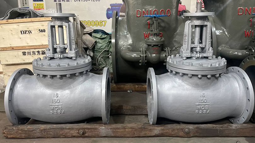
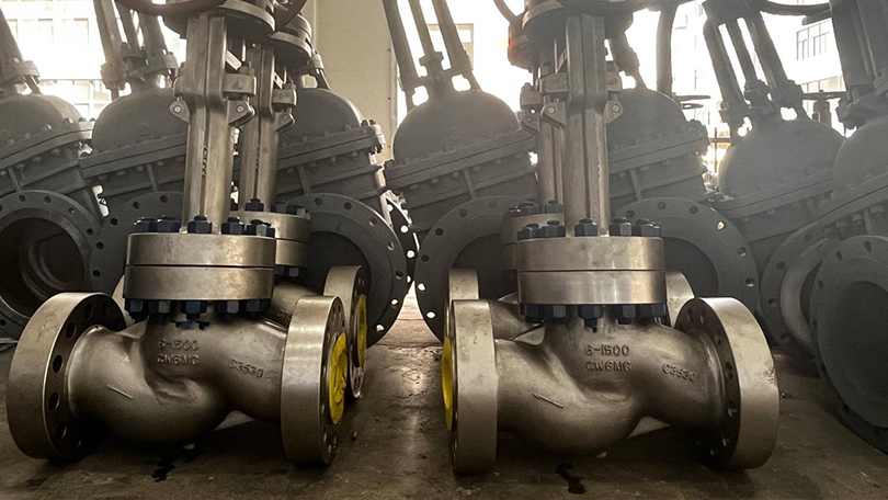
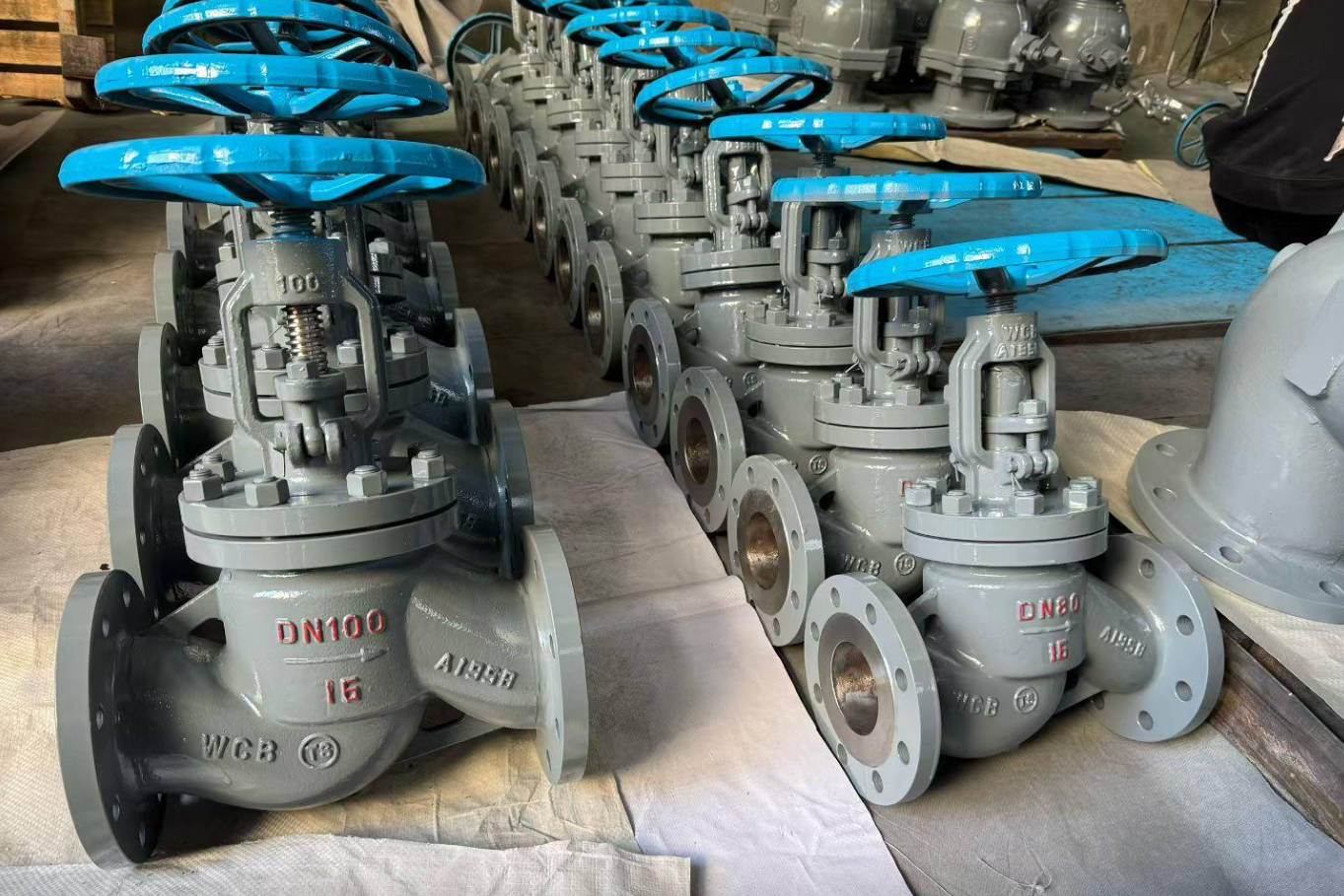
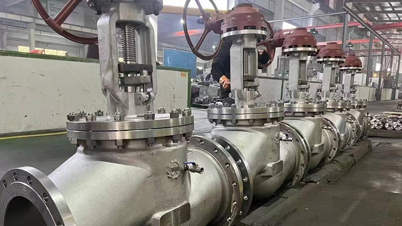
\n\n\n\n Valve Selection Guide归档 - Page 2 of 2 - Vornet Valve 838209&ev=PageView&noscript=1" />
jessamynlee@vornetvalve.com / jessamyn@vornetvalve.com 📞 +86-17888190118 🌐 EN

Industrial Valve Materials & Trim Equivalents: A Complete Selection Guide

📌 Quick Summary:

This guide covers valve body materials (carbon steel, stainless steel, and alloys), the API Trim numbering system (Trim 1 through 18), a step-by-step material selection framework, and industry-specific recommendations for oil & gas, chemical, power generation, cryogenic, seawater, and food processing applications.

📋 Key Takeaways

  • ASTM A216 WCB (carbon steel) and A351 CF8M (stainless) are the most common body materials for general-service valves.
  • API Trim numbering system (Trim 1 through Trim 18) standardizes seat, disc, and stem material combinations for interchangeability.
  • Material selection depends on fluid corrosiveness, operating temperature, pressure class, and industry-specific standards like NACE MR0175.
  • Trim equivalents enable engineers to source compatible valve internals from different manufacturers with confidence.

Selecting the right valve material and trim combination is one of the most critical decisions in industrial valve engineering. An incorrect choice leads to premature failure, costly downtime, and safety hazards. This valve material selection guide covers the body materials and internal trim equivalents used across gate, globe, check, and ball valves — referencing ASTM, ASME, and API standards that matter in real-world procurement. For specific product applications, browse our gate, globe, and check valves or review our Hastelloy vs Titanium corrosion guide for specialized alloy requirements.

Industrial Valve Materials

1. Valve Body Materials – Specifications & Equivalents

Carbon Steel Body Materials

WCB (ASTM A216 Grade WCB) — The most widely used carbon steel for general-service valves. Suitable for non-corrosive and mildly corrosive media such as water, oil, and gas at temperatures from −29°C to 425°C. Equivalent to DIN 1.0619, JIS SCPH2, and GB WCB.

WCC (ASTM A216 Grade WCC) — Higher-strength variant of WCB with improved impact properties at low temperatures. Used in higher-pressure applications and larger valve sizes. Equivalent to DIN 1.0625, JIS SCPH2-H.

LCB (ASTM A352 Grade LCB) — Low-temperature carbon steel for services down to −46°C. Essential for cryogenic and cold-climate applications. Equivalent to DIN 1.0619 + impact test, JIS SCPL1.

LCC (ASTM A352 Grade LCC) — Higher-strength low-temperature carbon steel with improved notch toughness. Used for critical low-temperature services below −46°C. Equivalent to DIN 1.0650, JIS SCPL2.

Forged Steel: A105 — The standard forged carbon steel for valves, flanges, and fittings. Operating range −29°C to 425°C. For low-temperature service, use A350 LF2 (down to −46°C).

Stainless Steel Body Materials

CF8 (ASTM A351 Grade CF8) — Cast 304 stainless steel. Excellent corrosion resistance in oxidizing environments, food processing, and mild chemical service. Temperature range −254°C to 649°C. Equivalent to DIN 1.4308, JIS SCS13A, GB CF8.

CF8M (ASTM A351 Grade CF8M) — Cast 316 stainless steel with molybdenum addition for improved pitting and crevice corrosion resistance. Ideal for seawater, chemical processing, and pulp & paper industries. Equivalent to DIN 1.4408, JIS SCS14A, GB CF8M.

CF3 (ASTM A351 Grade CF3) — Low-carbon 304L equivalent for welded construction where sensitization and intergranular corrosion are concerns. Equivalent to DIN 1.4306, JIS SCS19A.

CF3M (ASTM A351 Grade CF3M) — Low-carbon 316L equivalent for superior weldability and corrosion resistance in aggressive chemical environments. Equivalent to DIN 1.4409, JIS SCS16A.

Forged Equivalent: A182 F304 / F316 — Forged stainless steels for smaller valves and high-pressure applications where cast porosity cannot be tolerated.

Alloy & Special Alloy Body Materials

WC6 (ASTM A217 Grade WC6) — 1.25% Chrome, 0.5% Moly alloy steel for elevated temperature service up to 593°C. Common in power generation and refinery applications. Equivalent to DIN 1.7357, JIS SCPH21.

WC9 (ASTM A217 Grade WC9) — 2.25% Chrome, 1% Moly alloy steel for high-temperature and high-pressure steam services. Used extensively in supercritical power plants. Equivalent to DIN 1.7379, JIS SCPH32.

C5 (ASTM A217 Grade C5) — 5% Chrome, 0.5% Moly alloy for moderate corrosion and high-temperature resistance. Suitable for refinery sour service. Equivalent to DIN 1.7363.

Duplex & Super Duplex (ASTM A890 Grade 4A/5A) — High-strength stainless steels with excellent chloride stress corrosion cracking resistance. Grade 4A (UNS S31803/S32205) for oil & gas offshore, Grade 5A (UNS S32750) for the most aggressive seawater and chemical services.

Nickel Alloys — Monel (ASTM A494 Grade M35-1) for hydrofluoric acid and seawater; Hastelloy C-276 (ASTM A494 Grade CW-12MW) for extreme oxidizing and reducing environments; Titanium (ASTM B367 Grade C-2) for bleach and chlorinated services.

Industrial Valve Materials

2. Valve Trim Materials – API Trim Numbering System

Common API Trim Designations

API TrimSeat / Disc MaterialStem MaterialTypical Application
Trim 1F6a (13% Cr / 410 SS)13% Cr / 410 SSGeneral service, water, oil, gas up to 425°C
Trim 5Stellite (Co-Cr alloy)18-8 SS (304 SS)High temperature, erosive services, steam
Trim 8Stellite13% Cr / 410 SSHigh temperature with improved stem strength
Trim 11Full Stellite (seating surfaces)Hastelloy CHighly corrosive & high-temperature combined
Trim 12316 SS (full hard)316 SSCorrosive chemical service, food processing
Trim 16MonelMonel / K-MonelHydrofluoric acid, seawater, sour gas
Trim 17Hastelloy CHastelloy CSevere corrosive environments, bleach, wet Cl₂

Note: Trim numbers vary slightly between API 600 (gate valves) and API 602 (forged steel gate/globe/check valves). Always verify the trim table in the applicable standard.

Trim Material Selection by Service Condition

13% Chromium Stainless Steel (410 SS / F6a) — Hardness typically 250-350 HB. Suitable for clean hydrocarbons, water, steam, and mild chemical media. Not recommended for chloride environments above 50 ppm or where hydrogen sulfide is present above NACE MR0175 limits.

18-8 Stainless Steel (304 SS) — Lower hardness (~150 HB) but superior corrosion resistance. Used in chemical, food, and pharmaceutical services. Often hard-faced with Stellite for seating surfaces to improve wear resistance.

Stellite (Co-Cr-W Alloy) — The premier hard-facing material for valve seats and discs. Excellent galling resistance, hot hardness up to 650°C, and outstanding erosion resistance. Applied via welding overlay on the seating surfaces of the seat ring and disc/wedge. Essential for high-temperature steam, erosive slurries, and frequent cycling services.

316 Stainless Steel — Molybdenum-bearing austenitic stainless steel with improved pitting resistance. FAA (Full Austenitic) trim for corrosive chemical and seawater applications. Not as hard as 410 SS — consider hard-facing for abrasive services.

Monel (400 / K-500) — Nickel-copper alloy with exceptional resistance to hydrofluoric acid, seawater, and neutral/alkaline salt solutions. K-500 offers age-hardening for higher strength. Standard trim for HF alkylation units, marine systems, and sour gas handling.

Hastelloy C-276 — Nickel-chromium-molybdenum alloy with near-universal corrosion resistance. Handles wet chlorine, ferric/copper chlorides, strong oxidizing acids, and hot contaminated mineral acids. Used when no other trim material survives.

Industrial Valve Materials

3. How to Select the Right Material & Trim Combination

Step 1: Define the service conditions

  • Fluid composition and concentration
  • Operating and design temperature range
  • Operating and design pressure
  • Flow velocity and erosive potential
  • Cycling frequency

Step 2: Check industry standards

  • NACE MR0175 / ISO 15156 — Mandatory for sour oil & gas environments containing H₂S. Limits hardness of trim materials (typically ≤ HRC 22 for carbon/low alloy, ≤ HRC 40 for 410 SS, ≤ HRC 35 for duplex).
  • ASME B16.34 — Defines pressure-temperature ratings based on body material group. Refer to ASTM International for official material specifications and testing requirements.
  • API 600 / 602 / 608 — Specify trim material requirements for gate, globe, check, and ball valves.

Step 3: Evaluate corrosion mechanisms

  • General corrosion → Upgrade from carbon steel to 304/316 SS or higher alloy.
  • Pitting & crevice corrosion → MO (Molybdenum) content matters. CF8M (2-3% Mo) > CF8.
  • Stress corrosion cracking (SCC) → Avoid austenitic SS in hot chloride environments. Use duplex or nickel alloys.
  • Sulfide stress cracking (SSC) → NACE compliance required. Hardness control is critical.
  • Erosion & cavitation → Stellite hard-facing on seating surfaces. For severe cavitation, consider anti-cavitation trim designs.

Step 4: Material equivalency check

When procuring from different global regions, always cross-reference material specifications. A CF8M (ASTM) body may be quoted as 1.4408 (DIN), SCS14A (JIS), or Z3CNUD19-10 (NF). The chemical composition and mechanical properties must meet or exceed the specified standard. Vornet Valve provides material test certificates (MTC / EN 10204 3.1) with every order for traceability.

4. Material Selection Quick Reference by Industry

IndustryRecommended Body MaterialRecommended Trim
Oil & Gas (Sweet)WCB / A105Trim 1 (13% Cr)
Oil & Gas (Sour / NACE)WCB / A105 (NACE)Trim 1 or 5 with hardness control
Chemical ProcessingCF8M / A182 F316Trim 12 (316 SS) or Trim 5
Power Generation (Steam)WC6 / WC9Trim 5 or 8 (Stellite seat)
Cryogenic (−196°C)CF8 / CF8M / A182 F304Trim 12 (full 316)
Seawater / OffshoreDuplex (A890 4A/5A)Duplex / Super Duplex
Hydrofluoric AcidMonel / Carbon SteelTrim 16 (Monel)
Pulp & Paper (Bleach)Hastelloy C / TitaniumTrim 17 (Hastelloy)
Food & PharmaceuticalCF8 / CF3 (304/304L)Trim 12, full SS

Valve Material Selection Guide Summary: Why Correct Material Selection Matters

Valve material and trim selection directly impact equipment life, safety, and total cost of ownership. A WCB valve with Trim 1 may cost 50% less than a CF8M valve with Stellite trim — but if the service is wet chlorine, the WCB valve will fail within hours.

Always start with a clear understanding of the process fluid, temperature, pressure, and applicable code requirements. When in doubt, consult the valve manufacturer with a completed data sheet — most premature valve failures trace back to incomplete or incorrect material specifications at the procurement stage.

At Vornet Valve, we manufacture valves in carbon steel, stainless steel, duplex, Monel, Hastelloy, and titanium — with all standard API trims. Each valve is tested and certified to the applicable standard, ensuring full traceability from melt to final assembly.

Need help selecting the right material for your application? Contact our engineering team with your service conditions, and we’ll recommend the optimal body material and trim combination.

Industrial Valve Materials

Frequently Asked Questions

Q1: What is the difference between WCB and WCC valve bodies?

Both are cast carbon steels per ASTM A216. WCC has higher tensile and yield strength than WCB, with improved impact properties, making it suitable for higher-pressure services and larger valve sizes.

Q2: What does API Trim 5 mean?

API Trim 5 specifies Stellite hard-facing on the seating surfaces (seat ring and disc) with an 18-8 stainless steel stem. It is the most common trim for high-temperature and erosive services.

Q3: Can I substitute CF8M with CF8 in a chemical service?

Not without checking the specific chemical environment. CF8M contains 2-3% molybdenum, which provides significantly better pitting and crevice corrosion resistance than CF8. Substituting CF8 for CF8M in chloride-containing environments will likely result in rapid pitting failure.

Q4: What trim is required for NACE MR0175 compliance?

NACE MR0175 doesn’t mandate a specific trim number but requires hardness control of all pressure-containing and trim materials. For carbon steel bodies, Trim 1 with hardness-controlled 410 SS (≤ HRC 22 or ≤ HRC 40 depending on application) is common. Always verify the specific NACE environment classification.

Q5: What is the maximum temperature for Stellite hard-facing?

Stellite (Co-Cr-W alloy) maintains its hardness up to approximately 650°C (1200°F). Above this temperature, the hard-facing may soften, and alternative materials or cooling designs should be considered.

Q6: What material is used for cryogenic ball valves?

Cryogenic ball valves (down to −196°C / −320°F) typically use CF8M (316 SS) bodies with full 316 SS internals, extended bonnets, and low-temperature impact-tested components. PTFE or PCTFE seat materials are used for the sealing surfaces.

Need Help Selecting Valve Materials for Your Project?

Vornet Valve manufactures valves in carbon steel, stainless steel, duplex, and exotic alloys (Hastelloy, Monel, Titanium, Inconel) with API Trim 1 through 18 options. Contact us for material selection assistance.

Request a Quote →

What Is a Control Valve? Complete Guide to Types, Features, and Applications

📋 Key Takeaways

  • Control valves modulate fluid flow using an actuator-driven closure element positioned by a controller signal.
  • Major control valve types include globe, ball, butterfly, plug, diaphragm, and pinch valves, each with distinct flow characteristics.
  • Globe valves offer linear flow characteristics ideal for throttling; ball and butterfly valves suit on-off and modulating services.
  • Proper actuator sizing, positioner calibration, and flow coefficient (Cv) selection are essential for accurate loop control.
📌 What You’ll Learn:

Control valve types — globe, rotary ball, butterfly, cage-guided, and diaphragm — how actuators and positioners work, flow characteristics (linear, equal percentage, quick opening), critical selection criteria including Cv, pressure drop, and noise control, plus a complete Class 300 selection guide with actuator sizing tables. This guide covers everything from basic control valve principles to advanced applications across oil and gas, power generation, chemical, water, pharmaceutical, and food industries.

This control valve selection guide covers types, sizing, actuators, positioners, and applications for industrial process control. A control valve is a power-operated device used to regulate the flow rate, pressure, temperature, or level of a process fluid by varying the size of the flow passage as directed by a control system signal. Unlike manual valves that require a human operator to turn a handwheel, a control valve receives an electronic or pneumatic signal from a process controller and automatically positions its internal throttling element — such as a plug, ball, or disc — to maintain the desired process variable at its setpoint.

Control valves are the final control element in nearly every industrial process loop. They work in conjunction with sensors (transmitters) that measure the process variable and controllers (PLCs, DCS, or standalone PID controllers) that compare the measured value to the setpoint and generate an output signal. The control valve receives this signal through its actuator and positioner, adjusts its opening position accordingly, and thereby influences the process condition to match the setpoint. This closed-loop control architecture forms the foundation of modern industrial automation.

The global control valve market was valued at approximately USD 8.5 billion in 2025 and is projected to exceed USD 12 billion by 2032, driven by increasing automation in oil and gas, power generation, chemical processing, water treatment, and pharmaceutical manufacturing. Ultimately, Control valves are manufactured in sizes from NPS 1/2″ to 48″ and pressure classes from Class 150 to Class 4500, in materials ranging from cast carbon steel to exotic alloys such as Hastelloy, Monel, and Inconel. Design, testing, and performance criteria are governed by international standards including IEC 60534, ISA 75.01, ASME B16.34, and API 598.
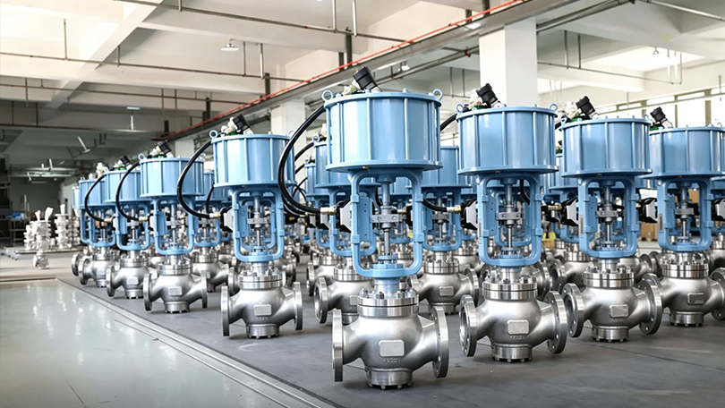
Control Valve

How Does a Control Valve Work? — Control Valve Types

A control valve operates through the coordinated action of three primary subsystems: the valve body (which contains the flow-controlling element), the actuator (which provides the motive force to position the element), and the positioner (which precisely controls the actuator’s position in response to the control signal).

The operating sequence is as follows: A process transmitter measures the actual process variable (flow rate, pressure, temperature, or level) and sends a 4-20 mA signal to the controller. The controller compares this value to the desired setpoint and calculates an error. Based on the error, the controller generates a control output signal (typically 4-20 mA or 3-15 PSI pneumatic). The control valve’s positioner receives this signal, compares it to the actual valve stem position (feedback by a mechanical linkage or magnetic sensor), and adjusts the pneumatic or electric power delivered to the actuator. The actuator moves the valve stem to a new position, changing the flow area through the valve until the process variable reaches the setpoint.

The total response time — from the moment the controller detects a process deviation to the moment the valve stem reaches its new position — is typically 1 to 10 seconds depending on valve size, actuator type, and process dynamics. This closed-loop correction cycle repeats continuously, often several times per second, to maintain stable process conditions.
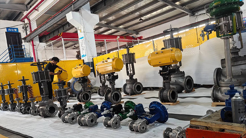
Control Valve

Key Components of a Control Valve Assembly

A complete control valve assembly consists of several components that work together to provide accurate, reliable flow control. Understanding each component is essential for proper selection, installation, and maintenance.

Valve Body

The valve body houses the internal trim (seat, disc/plug, cage, stem) and contains the process fluid under pressure. It provides the flow path and connection to the piping system. Body materials are selected based on pressure class, temperature, and fluid corrosivity — ranging from WCB carbon steel for general service to CF8M stainless steel, WC6/WC9 alloy steel, and Hastelloy for severe service. End connections include flanged (raised face, RTJ), threaded, butt-weld, socket-weld, and clamp-type (sanitary).

Actuator

The actuator provides the mechanical force required to position the valve’s throttling element. Actuators are classified by their power source: pneumatic (spring-diaphragm or piston), electric, electro-hydraulic, or manual (handwheel for backup). The actuator must generate sufficient thrust to overcome the unbalanced forces from process pressure, packing friction, and flow-induced forces at all valve positions. Actuator sizing is one of the most critical steps in control valve selection.

Positioner

The positioner is a precision control device mounted on the actuator that receives the control signal (4-20 mA, 3-15 PSI, or digital fieldbus) and adjusts the actuator’s position accordingly. It compares the input signal to the actual valve stem position (feedback signal) and modulates the actuator supply pressure or power until the positions match. Modern digital positioners (also called smart positioners) offer advanced features including HART or Foundation Fieldbus communication, auto-calibration, diagnostic monitoring, valve signature analysis, and predictive maintenance alerts.

I/P Transducer

The current-to-pressure (I/P) transducer converts a 4-20 mA electronic control signal into a proportional 3-15 PSI pneumatic signal for the positioner or actuator. In smart digital positioners, the I/P function is integrated within the positioner electronics. For analog systems, a stand-alone I/P transducer is used. Accuracy, air consumption, vibration resistance, and response time are key selection criteria for I/P transducers.

Accessories

Common control valve accessories include: air filter regulators (to provide clean, regulated supply air), solenoid valves (for on-off shutoff or emergency shutdown), volume boosters (to increase actuator speed), limit switches (for remote position indication), and locking devices or handwheels (for manual backup operation during instrument air failure).
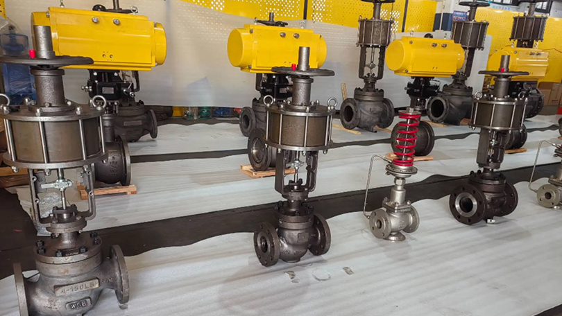
Control Valve

Control Valve Selection Guide: Types of Control Valves

Control valves are classified by the motion of the internal throttling element (linear vs. rotary stroke) and by the internal trim design. Each type has distinct advantages for specific applications, pressure ranges, and fluid characteristics.

1. Globe-Style Control Valve

The globe-style control valve uses a linear-motion plug that moves perpendicular to the seat ring to regulate flow. Specifically, It is the most widely used control valve type in the process industry, offering excellent throttling accuracy, a wide range of Cv values, and compatibility with high-pressure and high-temperature services. The flow path through a globe control valve changes direction, creating a predictable pressure drop that enables stable control even under varying process conditions. Globe-style control valves are available in single-port (for standard throttling) and double-port (for reduced actuator force requirements in high-pressure applications) configurations. Cage-guided globe valves (described below) are the most common variant.

2. Rotary Control Valve (Ball Valve)

Rotary control ball valves use a quarter-turn (90-degree) rotating ball with a cylindrical or segmented bore to regulate flow. The ball rotates from fully open (bore aligned with flow path) to fully closed (solid face blocking flow). Segmented ball valves (also called V-notch or V-port ball valves) use a V-shaped notch in the ball that provides an equal-percentage flow characteristic ideal for control applications. Rotary control ball valves offer high flow capacity (Cv), tight shutoff, low cost relative to globe valves of the same size, and resistance to clogging in dirty or viscous services. They are widely used in pulp and paper, mining, oil and gas, and water treatment applications.

3. Rotary Control Valve (Butterfly Valve)

Butterfly control valves use a rotating disc that pivots in the center of the pipe to regulate flow. High-performance butterfly valves with eccentric disc designs (double-offset and triple-offset) provide excellent throttling characteristics, bubble-tight shutoff, and long service life. Butterfly control valves are the most economical choice for large pipe sizes (NPS 6″ and above) and are widely used in water distribution, HVAC, power plant cooling water, and low-pressure gas applications. Their compact face-to-face dimensions and lightweight construction reduce installation cost and piping support requirements.

4. Cage-Guided Control Valve

Cage-guided control valves are a specialized type of globe-style valve where the plug moves within a cylindrical cage that serves both as a flow-directing element and as a plug alignment guide. The cage contains precisely machined openings (ports) that determine the flow characteristic — linear, equal percentage, or quick opening — without changing the plug or seat. Cage guidance provides superior vibration dampening, reduced noise generation, and protection against side-loading of the stem. Cage-guided valves are the preferred choice for high-pressure drop applications, services with high fluid velocities, and applications requiring anti-cavitation or low-noise trim. The cage also facilitates easy trim replacement without removing the valve body from the pipeline.

5. Diaphragm Valve

Diaphragm valves use a flexible membrane (diaphragm) clamped between the valve body and bonnet. When the actuator pushes a compressor down onto the diaphragm, it seals against a weir in the body, throttling flow. When lifted, flow passes freely over the weir. Diaphragm valves are ideal for sanitary, pharmaceutical, food, and bioprocessing applications because the weir-body design eliminates crevices and dead spaces where bacteria could grow. The diaphragm completely isolates the bonnet and actuator from the process fluid, making these valves suitable for corrosive or sterile media. Materials include PTFE, EPDM, and silicone diaphragms with body materials of 316L stainless steel, PVC, CPVC, and polypropylene.
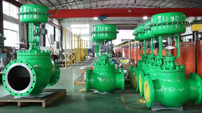
Control Valve

Control Valve Flow Characteristics

The relationship between the valve’s opening (stem travel) and the resulting flow rate (Cv) is called the flow characteristic. For example, Selecting the correct characteristic is critical for stable process control. The three standard characteristics per IEC 60534 are described below.

Linear Characteristic

In a linear characteristic valve, the flow capacity (Cv) increases proportionally with stem travel. A 50% stem position produces approximately 50% of the full-open Cv. Linear characteristics are best suited for processes where the pressure drop across the valve remains relatively constant regardless of flow rate — such as level control in tanks, flow control with constant differential pressure, and certain temperature control applications. Linear valves provide consistent gain (change in flow per change in signal) across the entire operating range.

Equal Percentage Characteristic

Equal percentage (EQ%) is the most common characteristic for throttling control. In an equal percentage valve, equal increments of stem travel produce equal percentage changes in the existing flow coefficient. For example, moving from 50% to 60% travel might increase Cv by 25% of the current value, while moving from 60% to 70% travel also increases Cv by 25% of the new value. This characteristic compensates for the decreasing pressure drop across the valve as flow increases in a typical system. Equal percentage valves provide stable control across a wide range of process conditions and are the default choice for pressure control, temperature control, and flow control in systems with varying differential pressure.

Quick Opening Characteristic

Quick opening valves provide maximum flow increase at the beginning of stem travel. A small initial stem movement (10-20% travel) produces a large change in Cv (typically 70-80% of full Cv). Quick opening characteristics are used primarily for on-off and emergency shutdown applications where rapid flow initiation is required. They are also used in relief valve and dump valve applications. Quick opening is not recommended for precise throttling control because the gain is very high at low openings and very low at high openings, making stable control difficult.

Actuator Types for Control Valves

The actuator is the power source that positions the control valve’s internal element. The choice of actuator type depends on the available utility supply, required thrust, stroking speed, fail-safe requirements, and environmental conditions.

Pneumatic Spring-Diaphragm Actuator

The spring-diaphragm actuator is the most common actuator type in the process industry. It consists of a flexible diaphragm connected to the valve stem through a spring-loaded plate. Pneumatic pressure applied to the diaphragm chamber compresses the spring and moves the stem. Loss of supply air causes the spring to return the stem to its fail-safe position (fail-open or fail-closed depending on spring orientation). Advantages include simple construction, low cost, reliable fail-safe operation, and a long service life. Limitations include limited thrust capability (typically suitable up to Class 600 for smaller valves) and susceptibility to supply pressure variations.

Pneumatic Piston Actuator

Piston actuators use a piston in a cylinder instead of a diaphragm, supplied with pneumatic pressure. They generate significantly higher thrust than spring-diaphragm actuators of the same size and can operate at higher supply pressures (up to 150 PSI or more). Piston actuators are used for high-pressure control valves (Class 900 and above), large valve sizes, and applications requiring fast stroking speeds. Fail-safe operation requires an external spring module or a hydraulic/pneumatic fail-safe system since piston actuators do not have a built-in fail-safe spring as diaphragm actuators do.

Electric Actuator

Electric actuators use an electric motor (AC or DC) coupled to a gear train and a stem nut to convert rotary motion into linear or quarter-turn motion. They are self-contained units requiring only electrical power — no instrument air is needed. Modern electric actuators offer precise position control with resolution down to 0.1%, integrated positioners with fieldbus communication (Profibus, Modbus, Foundation Fieldbus), and fail-safe options using springs or batteries. Electric actuators are preferred in remote locations without instrument air supply, in clean rooms (no exhaust air), and in applications requiring data logging and sophisticated diagnostics. Their primary disadvantage is higher initial cost compared to pneumatic actuators.

Hydraulic Actuator

Hydraulic actuators use pressurized hydraulic fluid to generate very high thrust forces in a compact package. They are used for the most demanding control valve applications — very high pressure (Class 2500+), very large valve sizes (NPS 24″ and above), and applications requiring extremely fast stroking speeds or precise positioning under high unbalanced loads. Hydraulic actuators can maintain position without continuous power consumption using lock valves. They require a hydraulic power unit (pump, reservoir, accumulator) and are typically specified for specialized applications such as turbine control, high-pressure let-down stations, and subsea production systems.

Critical Selection Criteria for Control Valves

Proper control valve selection requires a thorough analysis of process conditions, fluid properties, and performance requirements. The following criteria are essential for correct sizing and selection.

Flow Coefficient (Cv)

The flow coefficient Cv is the number of US gallons per minute of water at 60°F that will flow through the valve with a 1 PSI pressure drop. Cv is the fundamental sizing parameter for control valves and is calculated using the standard ISA-75.01 sizing equations. The required Cv depends on the maximum and normal flow rates, inlet pressure, allowable pressure drop, specific gravity, temperature, and whether the flow is laminar, turbulent, or choked. Undersizing leads to insufficient flow capacity and excessive pressure drop; oversizing causes poor control at low flow rates (the valve operates near its closed position where gain is high and control is unstable). The general rule is to select a valve such that the normal operating position is between 50% and 80% open.

Pressure Drop and Choked Flow

The pressure drop across a control valve affects both the flow rate and the potential for cavitation or flashing. As flow velocity increases through the valve restriction, the static pressure drops. If the pressure at the vena contracta (the minimum cross-section area inside the valve) falls below the fluid’s vapor pressure, vapor bubbles form (flashing). If the bubbles subsequently collapse as pressure recovers downstream, cavitation occurs. Cavitation can cause severe physical damage to valve trim, noise, and vibration. The pressure recovery factor (FL) quantifies a valve’s tendency to cavitate — lower FL values indicate higher pressure recovery and greater cavitation risk. Anti-cavitation trim designs use multiple stages of pressure reduction to keep the pressure above vapor pressure throughout the valve.

Noise Prediction and Control

Control valves are a major source of noise in industrial plants, generated by turbulent flow, mechanical vibration, and cavitation. Valve noise is predicted using the IEC 60534-8-3 standard for aerodynamic noise and IEC 60534-8-4 for hydrodynamic noise. Excessive noise indicates high fluid energy dissipation that can damage trim components and cause piping vibration. Low-noise trim designs — including multi-stage pressure reduction, tortuous-path cages, and diffuser plates — reduce noise by 10-20 dBA compared to standard trim. For applications where noise must be controlled for occupational or environmental compliance, low-noise control valves, inline silencers, and acoustic insulation are available.

Rangeability and Turndown

Rangeability is the ratio of maximum controllable Cv to minimum controllable Cv. Turndown is the ratio of maximum to minimum flow rate the valve can control within acceptable accuracy. A valve with good rangeability (50:1 or higher) can handle both high-flow and low-flow conditions without requiring a second parallel control valve. Globe-style control valves typically offer rangeability of 30:1 to 50:1, while segmented ball valves can achieve 100:1 or higher. Rangeability requirements should be matched to process flow variations: batch processes with wide flow swings need high rangeability, while continuous processes with stable flow rates need moderate rangeability.

Control Valve vs. On-Off Valve: Key Differences

Control valves and on-off (isolation) valves serve fundamentally different purposes in a piping system. Understanding when to use each type is critical for proper system design and reliable operation.

CharacteristicControl ValveOn-Off Valve
Primary FunctionRegulate flow at any position between open and closedIsolation — fully open or fully closed only
PositioningModulated to any intermediate position (e.g., 45% open)Binary — either fully open (100%) or fully closed (0%)
ActuatorPositioner-controlled actuator with precise stem positioningSimple open/close actuator (spring-return or double-acting)
Throttling PrecisionExcellent — position accuracy within 0.5-1.0% of spanNone — not designed for intermediate positioning
Trim DesignSpecially profiled plug/cage for specific flow characteristicStandard gate, ball, or disc for maximum flow area
Cv vs. Pipe SizeLower Cv for same pipe size — designed for pressure dropHigher Cv — minimal pressure drop when fully open
Control SignalReceives 4-20 mA, 3-15 PSI, or fieldbus control signalReceives discrete on/off signal (24 VDC, 120 VAC, or pilot air)
Fail-Safe PositionMaintain last position, or move to fail-open/fail-closed on signal lossSpring-return to fail-open or fail-closed on power/air loss
Cycle LifeDesigned for frequent cycling (thousands to millions of cycles)Designed for infrequent operation (tens to hundreds of cycles per year)
CostHigher — positioner, smart electronics, precision trim add costLower — simpler actuator, no positioner, standard trim
Typical ServiceProcess control, flow regulation, pressure/temperature controlIsolation, block valve, emergency shutdown, on/off service

A critical design rule: never use an on-off valve for throttling service. Partial opening of a gate valve or ball valve designed for on-off service causes high-velocity flow across the seat, wire drawing, seat erosion, and premature failure. Conversely, a control valve may be used for isolation if it provides tight shutoff, but it is not the most economical choice when only isolation is required.

Applications by Industry

Control valves are used across nearly every industrial sector that requires automated process control. The following describes key applications by industry.

Oil and Gas. In upstream oil and gas, control valves regulate wellhead flow, gas lift injection rates, separator level control, and pipeline pressure. In midstream, they provide custody transfer flow control at metering stations, pipeline pressure regulation, and compressor station antisurge control. In downstream refineries, control valves are used in crude distillation, catalytic cracking, hydroprocessing, sulfur recovery, and product blending. Materials range from carbon steel for sweet service to stainless steel and Incoloy for sour gas (NACE MR0175 compliant) and high-temperature services. Pressure classes from Class 150 to Class 2500.

Power Generation. Power plants use control valves extensively for boiler feedwater regulation, steam temperature control (attemperation), turbine bypass control, condensate recirculation control, and cooling water systems. Additionally, High-pressure Y-type globe control valves with anti-cavitation trim are standard for supercritical and ultra-supercritical boiler applications. Quick-opening control valves are used for turbine bypass and safety-related services.

Chemical and Petrochemical. Chemical processing requires precise control of reactants, catalysts, and product flows. Notably, Control valves handle corrosive chemicals (acids, caustics, chlorides), high-temperature processes, and hazardous fluids. Sanitary diaphragm control valves are used in specialty chemical and pharmaceutical intermediate production. Materials include 316L stainless steel, Hastelloy C276, Monel 400, titanium, and PTFE-lined bodies.

Water and Wastewater. Municipal water treatment facilities use control valves for chemical dosing (chlorine, fluoride, coagulants, polymers), filter effluent flow control, filter backwash sequencing, and distribution system pressure regulation. Large butterfly control valves (NPS 24″ to 72″) are common in raw water intake and transmission mains. Globe control valves handle chemical injection with high turndown requirements.

Pharmaceutical and Biotechnology. In pharmaceutical manufacturing, control valves must meet FDA, cGMP, and USP Class VI requirements for clean-in-place (CIP) and sterilize-in-place (SIP) operations. Weir-type diaphragm control valves with 316L SS bodies, electropolished internal surfaces, and sanitary clamp connections are standard. Applications include WFI (water for injection) distribution, bioreactor temperature control, buffer preparation, and clean steam regulation.

HVAC and Building Management. Commercial building HVAC systems use control valves for hot water, chilled water, and condenser water regulation in heating and cooling coils, radiators, heat exchangers, and cooling towers. Characterized control ball valves and globe-style control valves with 0-10 VDC or 4-20 mA control signals are typical. Applications include VAV box reheat control, chiller plant optimization, and district heating/cooling networks.

Food and Beverage. Food and beverage processing uses CIP-compatible control valves for ingredient dosing, heat exchanger temperature control, carbonation, and packaging line flow regulation. Materials include 304L and 316L stainless steel with EPDM, silicone, or PTFE seals. Diaphragm control valves are preferred for viscous fluids, particulate-containing products, and applications requiring full drainability.

Control Valve Class 300 Selection Guide

The following selection guide provides a practical reference for specifying control valves in Class 300 applications, which are among the most common pressure classes in industrial process systems. Proper selection ensures reliable control, long service life, and cost-effective operation.

Table 1: Control Valve Type Selection by Service Condition (Class 300)

Service ConditionRecommended Valve TypeMax Cv (NPS 4″)Max TemperatureBest For
General throttling, clean fluidsGlobe-style (cage-guided)120-180425°C (WCB body)Water, steam, oil, gas
High-pressure drop, cavitating servicesGlobe-style (anti-cavitation cage)80-140425°C (WCB body)Boiler feedwater, condensate
High flow, low ΔP, clean fluidsRotary control ball (segmented V-ball)250-400350°C (316 SS body)Pulp stock, slurries, gas
Large pipe size, low ΔPHigh-performance butterfly (double-offset)400-2500+350°C (316 SS body)Water, air, HVAC, cooling water
Sanitary, sterile, food/pharmaWeir-type diaphragm valve40-150150°C (PTFE diaphragm)WFI, CIP, bioprocessing
Severe service, high noiseGlobe-style (low-noise cage trim)60-120425°C (WCB/WC6 body)High-pressure gas, steam vent
Corrosive fluidsGlobe-style (PTFE-lined or alloy body)50-100200°C (PTFE-lined)Acids, caustics, chlorides
Viscous or dirty fluidsRotary control ball (full-bore)300-500300°C (316 SS body)Slurries, heavy oils, polymers

Table 2: Actuator Selection Guide for Class 300 Control Valves

Valve SizeValve TypeBreakaway Torque/ThrustRecommended ActuatorSupply PressureFail-Safe
NPS 1″ – 2″Globe-style500-1500 lbfSpring-diaphragm (size 35-45)20-60 PSIIntegral spring
NPS 3″ – 4″Globe-style1500-4000 lbfSpring-diaphragm (size 50-70)20-80 PSIIntegral spring
NPS 6″ – 8″Globe-style4000-10000 lbfPiston actuator40-120 PSIExternal spring module
NPS 10″ – 16″Butterfly200-800 ft-lbSpring-diaphragm rotary (sizes 50-70)20-80 PSIIntegral spring
NPS 18″ – 24″Butterfly800-3000 ft-lbPiston rotary or electric (multi-turn)60-120 PSISpring-return or battery
NPS 1″ – 4″Rotary ball50-300 ft-lbSpring-diaphragm rotary (sizes 30-50)20-60 PSIIntegral spring
NPS 6″ – 12″Rotary ball300-1500 ft-lbPiston rotary or electric (multi-turn)40-120 PSIExternal spring or battery
NPS 1″ – 4″Diaphragm (weir)200-1000 lbfSpring-diaphragm (size 30-45)20-60 PSIIntegral spring

When selecting a control valve for Class 300 service, consider the following: (1) Cv requirements at both normal and maximum flow conditions; (2) Inlet pressure and allowable pressure drop based on system hydraulics; (3) Fluid properties including specific gravity, viscosity, vapor pressure, and solids content; (4) Process temperature range and ambient temperature conditions for the actuator; (5) Required flow characteristic (linear, equal percentage, or quick opening); (6) Rangeability requirements — batch processes with wide flow swings need high rangeability; (7) Fail-safe position requirements (fail-open, fail-closed, or lock-in-last-position); and (8) Communication protocol compatibility with the existing DCS or PLC system.
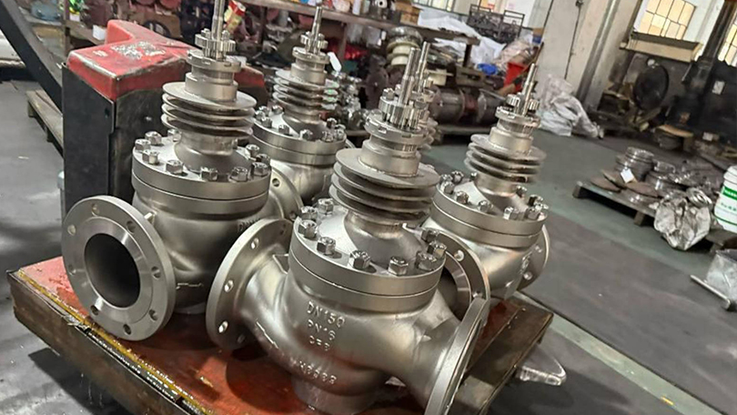
Control Valve

Conclusion

Control valves are the essential final control elements that make automated process control possible across virtually every industrial sector. From simple pressure regulation in a water treatment plant to high-pressure let-down in a petrochemical refinery, control valves translate electronic control signals into precise physical adjustments of flow area, enabling stable, safe, and efficient process operation. The selection of the correct control valve type — whether globe-style for precise throttling, rotary ball for high capacity, high-performance butterfly for large diameters, cage-guided for severe services, or diaphragm for sanitary applications — depends on a careful evaluation of process conditions, fluid properties, performance requirements, and lifecycle cost.

Key considerations in any control valve selection include the required flow coefficient (Cv), pressure drop and cavitation risk, noise predictions, rangeability, material compatibility with the process fluid, actuator type and fail-safe configuration, and communication protocol compatibility. The Class 300 selection guide provided in this article serves as a practical reference for the most common industrial control valve applications, covering valve type selection by service condition and actuator sizing by valve size and type.

As industrial automation advances with digitalization, Industry 4.0, and the Industrial Internet of Things (IIoT), control valves are evolving from simple mechanical regulators into intelligent field devices with embedded diagnostics, predictive maintenance capabilities, and wireless communication. Smart positioners with HART, Foundation Fieldbus, and PROFIBUS PA protocols enable condition monitoring, valve signature analysis, and real-time performance tracking that reduce unplanned downtime and optimize maintenance intervals. Selecting a control valve today means choosing not just a mechanical device, but a smart instrument that will integrate with the plant’s digital infrastructure for years to come.

Vornet Valve manufactures a comprehensive range of control valves in carbon steel (WCB, WCC, LCB), stainless steel (CF8, CF8M, CF3M), and alloy steel (WC6, WC9), with sizes from NPS 1/2″ to 24″ and pressure classes from Class 150 to Class 2500. Vornet control valves are designed with standard and custom trim options including anti-cavitation, low-noise, and erosion-resistant configurations. All Vornet control valves are designed, manufactured, and tested in accordance with IEC 60534, ASME B16.34, and API 598 standards, ensuring reliable performance in the most demanding process control applications.

Need a Control Valve for Your Process System?

Vornet Valve manufactures control valves in carbon steel, stainless steel, and alloy steel — NPS 1/2″ to 24″, Class 150 to 2500. Pneumatic, electric, and hydraulic actuation available.

Get a Quote →

What Is a Globe Valve? Complete Guide to Types, Features, and Applications

📌 Quick Summary:

Globe valves regulate flow through linear motion of a disc against a stationary seat, making them ideal for throttling, frequent operation, and precise flow control. This guide covers Z-type, Y-pattern, angle, and bellows seal globe valves with selection criteria for pressure, temperature, and media compatibility.

📋 Key Takeaways

  • Globe valves regulate flow via linear motion of a disc against a stationary seat, offering precise throttling control.
  • Z-type (tee-pattern) provides lowest cost but highest pressure drop; Y-pattern minimizes flow resistance for high-pressure service.
  • Angle-pattern globe valves eliminate an elbow fitting, while bellows-seal designs prevent stem leakage in hazardous fluids.
  • Needle valves offer fine flow regulation for instrumentation and small-bore applications with tapered disc-to-seat engagement.

however, This globe valve complete guide covers all major globe valve types including Z-type, Y-type, angle, bellows seal, and needle valves, with working principles, material selection, and sizing information for industrial applications.

additionally, This globe valve complete guide covers all major types, working principles, and selection criteria for industrial applications. A globe valve is a linear motion valve used to regulate or throttle flow in a pipeline. Named for its spherical body shape — though modern designs vary — the globe valve operates using a movable disc (or plug) that seats against a stationary ring seat. By raising or lowering the disc through a handwheel, actuator, or stem, the operator can precisely control the flow rate from fully open to fully closed. Unlike gate valves, which are designed primarily for fully open or fully closed service, globe valves excel at throttling and flow regulation, making them one of the most widely used valve types in industrial piping systems. For a broader overview of how globe valves compare with other valve types, see our comprehensive industrial valve selection guide.

The defining characteristic of a globe valve is the change in flow direction through the valve body. Fluid entering the valve must flow around the seat and disc mechanism, creating a pressure drop that enables precise throttling control. This design inherently produces more resistance to flow than a gate or ball valve of the same size, but delivers superior control accuracy and shutoff capability.

Globe valves are manufactured in sizes from NPS 1/2″ to 48″ and pressure classes from Class 150 to Class 4500, in materials ranging from carbon steel to high-nickel alloys. They are governed by design standards including ASME B16.34, API 602 (for small forged steel valves), and BS 1873 (for flanged steel globe valves).

Globe Valve

Globe valve types: How Does a Globe Valve Work?

The operating principle of a globe valve is straightforward: a handwheel or actuator rotates the valve stem, which moves the disc (or plug) perpendicular to the seating surface. When the disc lifts away from the seat, flow passes through the annular opening between disc and seat. The distance the disc travels determines the size of this opening and therefore the flow rate.

Key operating characteristics include:

Linear Stem Movement. The stem moves in a straight line (in-and-out) rather than rotating. On rising-stem globe valves, the stem position visually indicates how far the valve is open. Multi-turn actuation is standard — typically 5 to 15 turns from fully closed to fully open depending on valve size and seat design.

Flow Direction. Globe valves are designed for flow under the disc (standard) or over the disc depending on service. In standard installation, flow enters below the disc so that when the valve is partially open, fluid lifts the disc away from the seat. This configuration provides better control during opening. For high-pressure drop services, flow-over-disc installation reduces seat erosion when the valve is nearly closed.

Throttling Precision. The disc-to-seat geometry of a globe valve allows the operator to make fine adjustments to flow. A 1/4-turn of the handwheel on a typical 2″ globe valve changes the flow area by a predictable, repeatable amount. This precision is unmatched by quarter-turn valves (ball, butterfly) in throttling applications.

Globe Valve Complete Guide: Types of Globe Valves

Globe valves are classified by body design, disc design, and bonnet configuration. Each type is optimized for specific pressure, temperature, and flow conditions. The five most common globe valve types are described below.

Globe Valve

1. Z-Type Globe Valve (Standard Pattern)

The Z-type or standard pattern globe valve features a characteristic Z-shaped flow path. Fluid enters below the disc, makes a 90-degree turn upward through the seat area, then turns another 90 degrees to exit the valve. This configuration creates the highest pressure drop among globe valve designs but also provides the best throttling characteristics. Z-type globe valves are the most common and economical choice for general throttling applications. They are widely used in water, steam, air, and general process services across various industrial applications at pressures up to Class 600 and temperatures up to 425°C. Available in sizes NPS 1/2″ to 24″ with threaded, flanged, or butt-weld end connections.

2. Y-Type Globe Valve (High Pressure)

Y-type globe valves have the seat and stem angled at approximately 45 degrees relative to the pipeline axis (forming a Y shape). This straight-through flow path significantly reduces pressure drop compared to Z-type designs. Y-type globe valves are the preferred choice for high-pressure and high-temperature services, particularly in power generation and steam systems where pressure drop must be minimized. They are commonly specified for boiler feedwater isolation, main steam lines, and turbine bypass applications. The Y-type design also reduces seat erosion in high-velocity services because the flow path is less tortuous. Pressure classes up to Class 4500 and sizes up to NPS 24″ are available.

3. Angle Globe Valve

Angle globe valves combine a globe valve body with a 90-degree turn, serving as both a valve and a pipe fitting. The inlet and outlet are at right angles, eliminating the need for a separate elbow fitting. This design reduces the number of potential leak points, lowers installation cost, and minimizes pressure drop compared to a Z-type globe valve with a separate elbow. Angle globe valves are commonly used in boiler feedwater systems, heater drain applications, and high-pressure let-down stations where space is constrained. They are also preferred for cyclic service where the valve experiences frequent opening and closing, as the angle body reduces thermal and mechanical stress on the piping.

4. Bellows Seal Globe Valve

Bellows seal globe valves incorporate a metal bellows assembly between the stem and the bonnet, creating a leak-tight seal that prevents process fluid from escaping through the stem packing. The bellows are typically made from austenitic stainless steel (AISI 316L or 316Ti) or Inconel alloys and are welded to the stem at one end and the bonnet connection at the other. The primary advantage is zero fugitive emissions — these valves meet the most stringent environmental regulations including TA-Luft (Germany) and EPA Method 21 (USA). Bellows seal globe valves are essential in applications handling toxic, hazardous, flammable, or expensive fluids. They are widely used in chemical processing, pharmaceutical manufacturing, thermal oil systems, heat transfer fluid circuits, and steam systems where stem leakage cannot be tolerated. A secondary backup packing is usually provided above the bellows for added safety.

5. Needle Valve (Small Bore Globe Valve)

Needle valves are small globe valves (typically NPS 1/2″ and smaller) that use a tapered, needle-shaped disc for precise flow regulation. The needle disc fits into a matching conical seat, allowing extremely fine adjustment of the flow orifice. Needle valves are used primarily in instrumentation, sampling systems, chemical injection, and hydraulic control circuits where precise flow metering is required. They are available with threaded, compression, or tube-weld end connections in materials including 316 stainless steel, Monel, and Hastelloy. Maximum operating pressure can exceed 10,000 PSI (Class 6000+) for high-pressure instrumentation applications.

Globe Valve

Globe Valve vs. Gate Valve: Key Differences

Gate valves and globe valves are both linear motion valves but are designed for fundamentally different purposes. Understanding the distinctions is critical for proper valve selection.

CharacteristicGlobe ValveGate Valve
Primary FunctionThrottling and flow regulationIsolation (fully open or fully closed)
Flow PathTortuous (changes direction inside body)Straight-through (full bore)
Pressure DropModerate to high (10-30% of inlet pressure)Very low (nearly zero when fully open)
Throttling CapabilityExcellent — precise control at any positionPoor — causes seat erosion if used for throttling
Shutoff TightnessVery good — suitable for bubble-tight shutoffExcellent — wedge gate design provides tight seal
Operating SpeedMulti-turn (5-15 turns depending on size)Multi-turn (10-30 turns depending on size)
Flow Capacity (Cv)Lower for same pipe sizeHigher for same pipe size
Water Hammer RiskLower — gradual closure characteristicsHigher — can trap fluid in gate cavity
Seat ErosionModerate — flow impinges on seatHigh (when partially open) — wire drawing on seat
Typical CostModerate (more complex body casting)Lower (simpler body design)
Preferred ServiceControl, regulation, frequent cyclingIsolation, infrequent operation

The rule of thumb in valve selection: if the application requires flow control or throttling, choose a globe valve. If the application requires isolation with minimal pressure drop, choose a gate valve. Attempting to use a gate valve for throttling will quickly erode the seating surfaces, leading to leakage and premature failure.

Globe Valve

Applications by Industry

Globe valves are used across virtually every industrial sector that handles pressurized fluids. Their throttling capability and reliable shutoff make them indispensable in the following industries:

Oil and Gas. In upstream production, globe valves regulate flow from wellheads, control injection rates for waterflood and gas lift operations, and provide precision flow control in gathering systems. In midstream pipelines, they serve as control valves at pump stations and metering skids. In downstream refineries, globe valves are used for process control on crude distillation units, catalytic crackers, hydrotreaters, and product blending systems. Materials typically include WCB carbon steel for sweet service and CF8M stainless steel or WC6 alloy steel for sour and elevated-temperature services.

Power Generation. Power plants are the single largest application for high-pressure globe valves, particularly Y-type and angle designs. Globe valves control boiler feedwater flow, regulate steam extraction from turbines, provide condensate system control, and serve as turbine bypass valves. The ability to withstand high temperatures (up to 600°C) and pressures (up to Class 4500) makes Y-type globe valves standard equipment in supercritical and ultra-supercritical power plants.

Chemical and Petrochemical. Chemical processing requires precise flow control of reactants, catalysts, and intermediates. Globe valves with bellows seals are used extensively for toxic and hazardous chemicals. Needle valves provide fine metering for catalyst injection and additive dosing. Materials of construction range from 316L stainless steel for general chemical service to Hastelloy C276 and Monel for highly corrosive media such as hydrochloric acid, wet chlorine, and seawater.

Water and Wastewater. Municipal water treatment plants use globe valves for filter backwash control, chemical dosing (chlorine, fluoride, coagulants), and flow regulation in distribution systems. Wastewater treatment plants use globe valves for sludge handling, aeration control, and digester gas systems. Sizes typically range from NPS 2″ to 24″ in Class 150 and Class 300.

HVAC and Building Services. Globe valves are standard equipment in heating, ventilation, and air conditioning systems for controlling hot water, chilled water, and steam flow to coils, radiators, and heat exchangers. Their throttling precision makes them ideal for temperature control in large commercial buildings, hospitals, and data centers.

Pharmaceutical and Food Processing. In pharmaceutical and food-grade applications, globe valves with sanitary connections (clamp ends) and electropolished internal surfaces meet FDA and cGMP requirements for clean-in-place (CIP) and sterilize-in-place (SIP) operations. Materials are typically 316L stainless steel with PTFE or EPDM seat seals.

Material Selection for Globe Valves

The choice of body, bonnet, and trim materials for a globe valve is driven by operating conditions and fluid compatibility. The table below provides a selection guide for common globe valve materials per ASME B16.34 standards.

Material GradeASTM SpecMax TemperatureBest For
WCB (Carbon Steel)A216425°C (800°F)Water, oil, gas, steam — general purpose
WCC (Carbon Steel)A216425°C (800°F)Lower temperature services, better weldability than WCB
CF8 (304 SS)A351425°C (800°F)Corrosive media, food processing, nitric acid
CF8M (316 SS)A351425°C (800°F)Marine, chemical, chloride-containing services
WC6 (1.25Cr-0.5Mo)A217540°C (1000°F)Steam, high-temperature hydrocarbon processing
WC9 (2.25Cr-1Mo)A217595°C (1100°F)High-temperature steam, hydrogen service, creep-resistant
LCB (Low-temp Carbon)A352−46°C (−50°F)Cryogenic and cold-weather applications
LC3 (3.5% Nickel)A352−101°C (−150°F)Low-temperature natural gas processing

Trim Material Guidelines: For standard water and steam service at moderate temperatures, 13% chromium stainless steel (13Cr, A276 Type 410) is the standard disc and seat material. For corrosive services, specify 316 stainless steel trim. For high-temperature or high-velocity services where seat erosion is a concern, Stellite 6 (cobalt-based alloy) hardfacing on both the disc and seat ring provides superior wear resistance. For sour gas services per NACE MR0175/ISO 15156, trim materials must be limited to 22 HRC maximum hardness.

Installation Best Practices

Proper installation is essential for achieving the rated performance and service life of a globe valve. The following best practices should be observed:

Flow Direction. Globe valves have a marked flow direction arrow on the body. Most standard globe valves are designed for flow under the disc — the pressure lifts the disc away from the seat during opening, reducing operating torque. Installing a globe valve backward can cause the disc to lift off the seat under high pressure differentials, leading to loss of control and potential seat damage.

Orientation. Globe valves should be installed with the stem vertical or nearly vertical. For high-temperature steam applications (>400°C), the stem should be in the vertical position to prevent thermal binding and uneven thermal expansion of internal components. For horizontal pipelines, stem-up installation is standard, with the bonnet accessible for maintenance.

Pipe Support. Globe valves are heavier than equivalent gate or ball valves due to the thicker body walls and internal baffle. Ensure adequate pipe supports are installed on both sides of the valve to prevent excessive stress on the body and flange connections. For valves NPS 8″ and larger, consider independent valve supports rather than relying solely on pipe hangers.

Allow for Thermal Expansion. In high-temperature services (>300°C), thermal expansion of the piping system can impose additional stress on the valve end connections. Use flexible expansion joints or loops where necessary, and ensure flanged connections have adequate bolt stretch to maintain gasket compression at operating temperature.

Stem Protection. Globe valve stems are exposed and can be damaged during installation. Protect the stem from impact, weld spatter, and construction debris. Do not use the handwheel or actuator as a lifting point — use the designated lifting lugs or body sling points.

Gasket Selection. For flanged globe valves, select gasket materials compatible with the operating temperature and fluid. Spiral-wound gaskets with 316SS windings and flexible graphite filler are standard for most industrial services. For high-temperature steam, use spiral-wound gaskets with heat-treated filler rings. For low-temperature or cryogenic service, PTFE envelope gaskets may be preferred.

Selection Criteria for Globe Valves

Selecting the right globe valve requires systematic evaluation of the following factors:

1. Service Conditions. Determine the operating pressure, temperature, and fluid characteristics (clean, dirty, corrosive, viscous, hazardous). These parameters define the pressure class, body material, and trim requirements.

2. Flow Control Requirements. Evaluate the required Cv (flow coefficient), turndown ratio, and control characteristics. For applications requiring a wide range of flow rates (turndown > 10:1), specify a globe valve with a characterized disc (equal percentage or linear) or a cage-guided design for precise flow curve matching.

3. Shutoff Class. Globe valves are available with metal seats (Class IV per FCI 70-2 / ANSI/FCI 70.2) and soft seats (Class VI). Specify Class IV for general steam and high-temperature service. Specify soft-seat (PTFE or PEEK) Class VI for bubble-tight shutoff in gas, chemical, or fugitive-emission-sensitive applications.

4. End Connections. Flanged (RF or RTJ per ASME B16.5) for general service up to Class 2500. Butt-weld ends per ASME B16.25 for high-pressure, high-temperature service where flanged connections are not preferred. Threaded ends (NPT) for small-bore valves NPS 2″ and smaller. Socket-weld ends for small-bore, high-pressure service.

5. Actuation. Choose manual handwheel for infrequent operation and throttling. Choose gear-operated handwheel for valves NPS 8″ and larger or when operating torque exceeds 150 Nm. Choose pneumatic actuation for remote control and automated process systems. Choose electric actuation for precise positioning in SCADA-controlled facilities.

6. Fugitive Emission Requirements. For applications handling toxic, hazardous, or volatile fluids, specify bellows seal globe valves or valves with low-emission packing (graphite or PTFE chevron rings) meeting TA-Luft or ISO 15848-1 requirements.

Globe Valve Class 300 Selection Guide

Class 300 globe valves are the most commonly specified pressure class for industrial globe valve applications. Rated at 740 PSI (5.1 MPa) at 100°F per ASME B16.34, Class 300 globe valves offer an optimal balance of pressure capability, cost, and availability for the majority of process, power, and general industrial applications.

Class 300 Globe Valve Specifications at a Glance

SpecificationClass 300 Globe Valve
Pressure Rating @ 100°F740 PSI (5.1 MPa) — ASME B16.34
Size RangeNPS 1/2″ — 24″ (DN 15 — 600)
Body MaterialsWCB (A216), WC6 (A217), CF8M (A351), LCB (A352)
Bonnet DesignBolted bonnet, pressure seal bonnet (high-temp), welded bonnet (small bore)
End ConnectionsFlanged RF (ASME B16.5), Butt-Weld (ASME B16.25), Socket-Weld, Threaded
Design StandardBS 1873, ASME B16.34, API 602 (forged small bore)
Trim Options13Cr (A276 410), 316 SS, Stellite 6 hardfaced seat & disc
OperationHandwheel, gearbox, pneumatic actuator, electric actuator
Test StandardAPI 598 (hydrostatic shell, seat, backseat tests)
Leakage ClassClass IV (metal seat) or Class VI (soft seat) per FCI 70.2

Class 300 Globe Valve Selection by Service

Service ConditionRecommended TypeBody MaterialTrim
Water, air & general utilityZ-Type Globe ValveWCB (A216 Gr. WCB)13Cr / F6a
Steam up to 425°CZ-Type or Y-TypeWCB or WC613Cr + Stellite 6 seat
High-pressure steam >425°CY-Type Globe ValveWC9 (A217 Gr. WC9)Stellite 6 seat & disc
Hydrocarbon / refined oilZ-Type Globe ValveWCB or LCB13Cr / 316 SS overlay
Corrosive chemicalsZ-Type Bellows SealCF8M (A351 Gr. CF8M)316 SS / Alloy 20
HVAC / building servicesZ-Type Globe ValveWCB / Ductile Iron13Cr or PTFE soft seat
Toxic / hazardous fluidsBellows Seal Globe ValveWCB or CF8M316 SS + Stellite seat
Instrumentation / meteringNeedle Valve316 SS (A479)316 SS / Stellite tip

Class 300 is the most widely specified pressure class for globe valves across refining, petrochemical, power generation, and general industrial applications. When selecting, confirm that the body material is suitable for the minimum design temperature (MDMT) and that the trim materials are compatible with the process fluid chemistry. For services involving thermal cycling (frequent start/stop), Y-type and angle globe valves provide superior resistance to thermal fatigue compared to Z-type designs.

Globe Valve

Conclusion

Globe valves are essential flow control components in virtually every industrial fluid handling system. Their ability to provide precise, repeatable throttling — combined with reliable shutoff capability — makes them the valve of choice when control matters more than conductance. The five main types — Z-type standard, Y-type high-pressure, angle globe, bellows seal, and needle valve — cover the full spectrum of industrial applications from low-pressure HVAC circuits to supercritical power plant steam lines.

When selecting a globe valve, the primary decision criteria are: operating pressure and temperature (determining the Class and body material), throttling precision requirements (determining the disc and seat design), fluid compatibility (determining trim materials and seal type), and end connection compatibility with the existing piping system. The Class 300 selection guide provided in this article serves as a practical reference for the most common industrial globe valve applications.

Vornet Valve manufactures a comprehensive range of globe valves in carbon steel (WCB, WCC, LCB), stainless steel (CF8, CF8M, CF3M), and alloy steel (WC6, WC9), with sizes from NPS 1/2″ to 24″ and pressure classes from Class 150 to Class 2500. All Vornet globe valves are designed, manufactured, and tested in accordance with BS 1873, ASME B16.34, API 602, and API 598 standards, ensuring reliable performance in the most demanding industrial services.

Frequently Asked Questions

Q1: What is the main difference between a globe valve and a gate valve?
A globe valve is designed for throttling and flow regulation, using a disc that moves perpendicular to the seat to precisely control flow. A gate valve is designed for isolation (fully open or fully closed), using a wedge that slides in and out of the flow path. Globe valves create a significant pressure drop but offer excellent control; gate valves have minimal pressure drop when fully open but must not be used for throttling as it causes seat erosion and leakage.

Q2: Why is it called a globe valve?
The name comes from the original body design, which featured a spherical (globe-shaped) central chamber that housed the seat and disc mechanism. While modern globe valves may have different exterior shapes, the internal structure — a baffle with a circular seat that creates a change in flow direction — retains the globe valve name. The spherical body shape provided optimal pressure containment for the disc and seat assembly.

Q3: Can a globe valve be used for isolation (on/off) service?
Yes, globe valves can be used for isolation service and provide very good shutoff, particularly with soft seats that achieve bubble-tight Class VI shutoff. However, for applications where the valve is rarely operated and minimum pressure drop is required, a gate valve is the better choice. For applications that require both throttling and positive shutoff in the same valve — such as bypass circuits and control stations — a globe valve is the appropriate selection.

Q4: What does the pressure drop across a globe valve depend on?
The pressure drop across a globe valve depends on the valve size (flow area), the disc position (how far open the valve is), the flow rate (GPM or LPM), and the specific gravity of the fluid. For a fully open globe valve, the pressure drop is typically 10-30% of the inlet pressure, compared to 1-3% for a fully open gate valve. The Cv (flow coefficient) published by the manufacturer is used to calculate the exact pressure drop at a given flow rate using the formula: ΔP = SG × (Q / Cv)², where Q is flow rate and SG is specific gravity.

Q5: What is the maximum operating temperature for globe valves?
The maximum temperature depends on the body material and seat type. Standard carbon steel (WCB) globe valves are rated to 425°C (800°F). Alloy steel WC6 (1.25Cr-0.5Mo) extends this to 540°C (1000°F). Alloy steel WC9 (2.25Cr-1Mo) reaches 595°C (1100°F). For metal-seated globe valves with Stellite hardfacing, continuous operation at 595°C is achievable. For services above 595°C, special high-temperature alloys such as Inconel 625 or AISI 310 stainless steel are required, and valve design must account for reduced material strength at elevated temperatures per ASME B16.34 derating curves. All material specifications reference ASTM International standards.

Q6: How do I select between a Z-type and a Y-type globe valve?
Select a Z-type globe valve for general throttling applications where some pressure drop is acceptable and cost is a primary consideration. Select a Y-type globe valve for high-pressure (>Class 600) or high-temperature (>400°C) applications where pressure drop must be minimized, particularly in boiler feedwater, main steam, and turbine bypass systems. Y-type globe valves cost approximately 20-40% more than equivalent Z-type valves but offer 30-50% lower pressure drop and significantly better resistance to thermal fatigue and seat erosion in severe service conditions.

Q7: When should I specify a bellows seal globe valve?
Specify a bellows seal globe valve whenever the process fluid is toxic, flammable, hazardous, expensive, or environmentally regulated. Bellows seal globe valves are mandatory in many jurisdictions for applications handling benzene, hydrogen sulfide, chlorine, phosgene, thermal oil (heat transfer fluids), and other fugitive-emission-sensitive media. They are also recommended for steam systems where stem leakage would cause safety hazards or energy losses. Bellows seal valves meet TA-Luft and EPA Method 21 fugitive emission standards and provide zero measurable leakage from the stem seal for the life of the bellows (typically 10,000+ cycles).

Q8: What maintenance is required for globe valves in industrial service?
Routine maintenance includes: (1) Periodic stem seal adjustment — tighten packing nuts gradually as the packing wears, but avoid over-tightening which increases operating torque; (2) Seat leak testing — perform during each plant turnaround to verify shutoff integrity; (3) Disc and seat ring inspection — check for pitting, galling, wire drawing, and erosion, particularly on the downstream seat face; (4) Stem thread lubrication — apply high-temperature anti-seize lubricant to stem threads annually; (5) Bellows integrity testing — for bellows seal valves, perform a pressure test on the bellows chamber at each turnaround; (6) Gasket replacement — replace bonnet gasket whenever the valve is disassembled for internal inspection. For severe service applications (high-temperature steam, erosive fluids), inspection frequency should be increased to every 6-12 months.

For inquiries about globe valve selection, technical quotation, custom manufacturing, or bulk procurement of Class 150 to Class 2500 globe valves, contact our engineering team.

Need a Globe Valve for Your Application?

Vornet Valve manufactures a comprehensive range of globe valves in carbon steel, stainless steel, and alloy steel — Z-type, Y-type, angle, bellows seal, and needle valves — from Class 150 to Class 2500, NPS 1/2″ to 24″. All designed to BS 1873, ASME B16.34, and API 602 standards.

💬 WhatsApp Us✉ Email Us

📖 Related Guides:
Globe Valve Selection Guide
API 600 Gate Valve vs Globe Valve
Control Valve Selection Guide

🏭 Looking for a Reliable Globe Valve Manufacturer?

Vornet Valve is a China-based industrial valve manufacturer with over 20 years of experience. We manufacture globe valves to BS 1873, ASME B16.34, and API 602 standards — including Z-type, Y-pattern, angle, bellows seal, and needle globe valves. Available in sizes NPS 1/2″ to 24″, Class 150 to Class 2500, with materials from WCB carbon steel to Hastelloy C276. Our globe valves are used in oil & gas, power generation, chemical processing, and water treatment applications worldwide.

Contact us today for a quote or technical consultation:

API 600 Globe Valve vs Gate Valve: Key Differences and How to Choose

📌 Quick Summary:

This guide compares API 600 gate valves and globe valves — their design differences, flow characteristics, pressure ratings, cost considerations, and application-specific recommendations for isolation and throttling service.

📋 Key Takeaways

  • API 600 gate valves provide straight-through flow with minimal pressure drop for isolation (on/off) service.
  • API 600 globe valves deliver superior throttling and flow regulation due to their Z-path or Y-pattern flow design.
  • Gate valves cost less but operate slower; globe valves are preferred for frequent regulation and tight shut-off needs.
  • Both follow Class 150-2500 pressure ratings and use cast carbon/alloy steel bodies with renewable seat rings.

When selecting valves for high-pressure, high-temperature industrial applications, two of the most commonly compared types are API 600 gate valves and API 600 globe valves. While both follow the same pressure class standard (API 600), they serve fundamentally different purposes: gate valves are designed for isolation (on/off service), while globe valves excel at throttling and flow regulation.

API 600 Gate Valve vs Globe Valve: Quick Comparison

FeatureAPI 600 Gate ValveAPI 600 Globe Valve
Primary FunctionIsolation (on/off)Throttling & flow regulation
Flow PathStraight-through (low drop)Z-path or Y-pattern
Pressure RatingsClass 150-2500Class 150-2500
Size RangeNPS 2-60NPS 1/2-24
Temperature Range-196C to 680C-196C to 680C
MaterialsCarbon steel, stainless, alloyCarbon steel, stainless, alloy
Operation SpeedMulti-turn (slow)Multi-turn (slow)
CostLowerHigher

API 600 Globe Valve vs Gate Valve

What Is an API 600 Gate Valve?

An API 600 gate valve uses a wedge-shaped or parallel gate that moves perpendicular to the flow path. When fully open, the gate retracts entirely into the bonnet, creating a straight-through flow path with minimal pressure drop. To compare it against other isolation valve families before you specify, see our industrial valve selection guide.

API 600 Globe Valve vs Gate Valve

What Is an API 600 Globe Valve?

An API 600 globe valve uses a linear-moving disc that seats against a stationary ring. The flow path changes direction, making globe valves ideal for throttling and regulating flow.

Key Differences Explained

Flow Control: Isolation vs Throttling

The fundamental difference is purpose. A gate valve’s flat gate creates turbulence when partially open. A globe valve’s contoured disc handles throttling conditions. Never use a gate valve for flow regulation.

Pressure Drop

Gate valves have the lowest pressure drop when fully open. Globe valves have 3-5x higher pressure drop due to directional flow change.

Size Range

API 600 gate valves reach NPS 60. Globe valves typically cap at NPS 24.

Cost

Gate valves are 15-25% less expensive than globe valves of the same size and class.

When to Use Which

ApplicationRecommendedReason
Main pipeline isolationGate valveLowest pressure drop
Flow regulationGlobe valveDesigned for partial opening
Frequent operationGlobe valveGate seats wear faster
ESD/emergency shutdownGate valveReliable shut-off
Bypass linesGlobe valvePrecise flow control
Large piping (>24)Gate valveGlobe not commonly available

API 600 Globe Valve vs Gate Valve

Real-World Application Scenarios

Understanding the practical differences between API 600 gate valves and globe valves helps engineers make better procurement decisions across power, oil and gas, and other industrial applications. The following table shows typical use cases and which valve type is recommended:

ApplicationRecommended ValveReason
Pipeline main line isolationAPI 600 Gate ValveLow pressure drop, straight-through flow, infrequent operation
Boiler feedwater regulationAPI 600 Globe ValvePrecise flow control needed, throttling capability essential
Emergency shutdown (ESD) systemsAPI 600 Gate ValveFast positive isolation with tight shut-off
Bypass lines around control valvesAPI 600 Globe ValveManual throttling for maintenance bypass scenarios
Storage tank isolationAPI 600 Gate ValveNormally open or closed, no throttling required

For additional valve comparison guides, see our Gate Valve vs Ball Valve comparison and Safety Valve vs Relief Valve guide.

FAQ: API 600 Gate and Globe Valves

Can I use a gate valve for throttling?

No. Gate valves are for fully open or closed only. Partial opening erodes seating surfaces. Use a globe valve for throttling.

Which has better shut-off?

Both provide bubble-tight shut-off per API 598 testing. Globe valves often maintain seal integrity longer.

Are pressure ratings the same?

Yes. Both follow ASME B16.34 pressure-temperature ratings for their class.

Which is easier to maintain?

Globe valves are easier. The disc and seat are more accessible for lapping or replacement vs gate valves requiring bonnet removal.

How to Select Between API 600 Gate Valve and Globe Valve: Decision Framework

Choosing the wrong valve type for your application can lead to premature failure, higher operating costs, and unsafe conditions. Use this step-by-step decision framework to determine whether an API 600 gate valve or an API 600 globe valve is right for your specific application:

Decision FactorChoose Gate Valve If…Choose Globe Valve If…
Primary functionIsolation only (on/off)Flow regulation or throttling
Operation frequencyInfrequent (few cycles/month)Frequent (daily cycling)
Pressure drop toleranceMust be minimalModerate drop is acceptable
Pipeline sizeNPS 24 and aboveNPS 24 and below
Flow direction changeStraight line onlyDirection change OK
Budget priorityLower initial cost neededWilling to pay for regulation
Maintenance accessFull bonnet removal acceptableTop-entry maintenance preferred

For applications requiring precise flow control with frequent adjustment, always choose an API 600 globe valve. For mainline isolation with minimal pressure loss, choose an API 600 gate valve. See also our Gate Valve vs Ball Valve comparison for a broader perspective on isolation valves.

What is the cost difference between API 600 gate valves and globe valves?

API 600 globe valves typically cost 15-25% more than gate valves of the same size and pressure class. The price difference is due to the more complex internal geometry of globe valves (Z-path or Y-pattern) and the tighter machining tolerances required for throttling service. For Class 150-300 sizes NPS 2-12, expect a premium of $200-$2,000 depending on materials and trim specifications.

Can API 600 gate valves and globe valves be used for high-temperature applications above 500°C?

Yes, both API 600 gate valves and globe valves are suitable for high-temperature service up to 680°C (1256°F) when specified with appropriate materials. For temperatures exceeding 425°C, standard carbon steel bodies should be replaced with chromium-molybdenum alloy steel (ASTM A217 WC6 or WC9). The trim material should also be upgraded to Stellite-faced seats and 13% chrome stainless steel or Inconel for the disc/seat rings to maintain hardness and resist creep at elevated temperatures.

API 600 Globe Valve vs Gate Valve

Conclusion

Choose an API 600 gate valve for isolation with minimal pressure drop. Choose an API 600 globe valve for precise flow regulation. For assistance, contact Vornet Valve.

Related: Ball Valve Guide | API 600 Gate Valve

Need an API 600 Gate Valve or Globe Valve for Your System?

Vornet Valve supplies API 600 gate valves and globe valves in sizes NPS 1/2″ to 60″, Class 150 to 2500, in carbon steel, stainless steel, and alloy materials. Contact us for sizing and selection assistance.

Request a Quote →

Industrial Gate Valve Selection Guide: 7 Core Factors for B2B Pipeline Procurement

📋 Key Takeaways

  • Gate valves are designed for fully open or fully closed service, not for throttling flow.
  • Key selection factors include pressure class, temperature range, end connections, and sealing material.
  • Rising stem designs provide visual position indication; non-rising stems suit limited-space installations.
  • Proper bonnet and trim selection ensures compatibility with the media and operating conditions.

Therefore, Gate valves are among the most fundamental and widely deployed isolation valves in industrial piping systems worldwide. As a critical linear-motion on/off valve, forged steel gate valve selection guide, the gate valve provides full-bore unobstructed flow with minimal pressure drop when fully open, making it the preferred choice for mainline isolation, pigging operations, and high-capacity process pipelines. For B2B procurement professionals, EPC contractors, and plant maintenance teams, selecting the correct gate valve configuration directly determines system reliability, operational safety, and total lifecycle cost. This industrial gate valve selection guide systematically breaks down 7 core technical factors that drive gate valve procurement decisions across oil & gas, petrochemical, power generation, water treatment and marine industries.

However, Gate valves function by lifting a rectangular or wedge-shaped gate out of the flow path, providing a straight-through conduit with negligible turbulence. Unlike globe valves that throttle flow, gate valves are designed exclusively for full-open or full-closed service — partial opening causes gate vibration, seat erosion, and accelerated wear. Understanding this fundamental operational constraint is the first step toward proper gate valve sizing and material selection for industrial B2B pipeline projects.

1. Medium Property Analysis — Forged steel gate valve selection — Forged Steel Gate Valve Selection Guide

1.1 Chemical Property — Corrosivity Determines Body Material

Therefore, The chemical nature of the process medium is the single most critical factor determining gate valve body and trim material selection. Different corrosive environments demand specific metallurgical solutions:

  • Carbon Steel (WCB/WCC): Suitable for non-corrosive or mildly corrosive services — water, steam, oil, natural gas, and neutral hydrocarbon fluids at moderate temperatures. The most economical choice for general industrial water and hydrocarbon mainline isolation.
  • 304 Stainless Steel (CF8): Provides good oxidation and mildly acidic corrosion resistance. Suitable for food-grade, pharmaceutical, and atmospheric corrosive environments where chloride levels are low. Resists nitric acid and organic acid at ambient to moderate temperatures.
  • 316 Stainless Steel (CF8M): Molybdenum-enhanced austenitic stainless steel offering superior pitting resistance in chloride-bearing environments. The standard choice for chemical processing, marine atmosphere, coastal installations, and mildly acidic chloride-containing streams.
  • Duplex Stainless Steel (4A/5A): Combines high strength with excellent chloride stress corrosion cracking resistance. Ideal for seawater cooling, offshore platform firewater, and high-pressure corrosive gas production piping where both mechanical strength and corrosion resistance are required.
  • Hastelloy C276: Premium nickel-chromium-molybdenum alloy for extreme corrosive service — hydrochloric acid, hot sulfuric acid, wet chlorine gas, and high-temperature mixed acid environments. Reserved for the most aggressive chemical process duty where standard stainless grades fail.

1.2 Physical State — Particle-Laden Media Need Special Designs

Furthermore, Process fluids containing suspended solids, catalyst particles, slurry, or crystallization-prone media present unique challenges for gate valves. Standard wedge gate designs trap particulates between the wedge and seat faces, preventing full closure and causing seat scoring. For particle-laden pipelines, the following design adaptations are essential:

  • Specify parallel slide gate valves with floating seats that self-align and wipe clean during each stroke cycle
  • Incorporate body cavity flushing ports to purge accumulated solids from the valve body dead space
  • Select hard-faced seats with Stellite or tungsten carbide overlay for abrasion resistance
  • Consider knife gate valves with bevelled gate edges that cut through settled solids and fiber-laden slurries for specialized applications
  • For high-temperature catalyst-laden streams (FCCU, coker), specify guided-disc parallel gate designs with enlarged body cavities to prevent solid accumulation and gate jamming

2. Key Operating Condition Parameters — Forged steel gate valve selection

2.1 Working Pressure & Surge Pressure

However, Gate valve pressure class selection must account for both steady-state operating pressure and transient surge events. Industry-standard pressure ratings follow ASME B16.34 class designations:

  • Class 150: Standard duty for water, low-pressure steam, and general utility services up to 19.6 bar at ambient temperature
  • Class 300: Medium-pressure hydrocarbon, chemical process, and refinery transfer lines up to 51.1 bar
  • Class 600: High-pressure production manifolds, wellhead isolation, and compressor station piping up to 102.1 bar
  • Class 900 / 1500: High-integrity pressure isolation for deep-well production, supercritical steam, and high-pressure gas transmission
  • Class 2500: Extreme pressure service for ultra-deep wells, HIPPS-protected segments, and supercritical power plant applications

Therefore, For liquid pipelines subject to water hammer, the selected gate valve pressure class must exceed the maximum surge pressure by a minimum factor of 1.1 to prevent body joint leakage and seat deformation. Gas pipeline blowdown and emergency shutdown (ESD) surge scenarios must also be evaluated.

2.2 Operating Temperature & Extreme Temperature

Furthermore, Temperature extremes fundamentally alter material mechanical properties, seal integrity, and operational torque requirements. Gate valve material selection must align with the full operating temperature envelope:

  • Cryogenic Service (-196°C to -29°C): Extended bonnet designs with stainless steel body/bonnet in CF8M or CF3M. The extended bonnet moves the stem packing away from the cold zone to maintain seal integrity. LNG, liquid oxygen, and liquid nitrogen gate valves require degreased, moisture-free assembly and cryogenic type-testing per BS 6364.
  • Low Temperature (-29°C to 0°C): Low Carbon Steel (LCC) or 3.5% Nickel steel body per ASME B16.34 low-temperature requirements. Impact-tested materials per ASME SA-352 ensure ductile fracture behavior below the nil-ductility transition temperature.
  • Moderate Temperature (0°C to 425°C): Standard carbon steel WCB bodies with graphite-based flexible graphite stem packing and spiral-wound gaskets. This covers the majority of refinery, petrochemical and power plant gate valve applications.
  • High Temperature (425°C to 570°C): Chrome-molybdenum alloy steel bodies (WC6, WC9, C5, C12) with Stellite-hardfaced seat rings and gate guide rails. Required for superheated steam, hot oil, and high-temperature hydrocarbon services.
  • Extreme Temperature (>570°C): Austenitic stainless steel or nickel-alloy bodies with full hard-facing of all sliding contact surfaces. Reserved for refinery fired heater isolation, FCCU regenerator slide valve service, and supercritical boiler applications.

Temperature de-rating per ASME B16.34 pressure-temperature tables must be strictly applied — a Class 300 carbon steel gate valve rated at 51.1 bar at 38°C may only be rated for 25.9 bar at 425°C.

2.3 Pipeline Flow Rate & Nominal Diameter

Gate valves are inherently full-bore designs; the seat bore diameter matches the pipe internal diameter to minimize pressure drop and enable pigging. When sizing gate valves for process pipelines:

  • The valve DN (nominal diameter) should match the connecting pipe nominal diameter for mainline block valve service
  • For high-velocity gas pipelines (>30 m/s), verify that the gate at full-open position is clear of the flow stream to prevent flow-induced gate vibration
  • For liquid pipelines with flow velocity exceeding 5 m/s, verify that the gate seating forces overcome hydrodynamic lifting forces
  • Large-diameter gate valves (DN600 and above) typically require gear operators or powered actuation due to gate mass and seating/unseating thrust requirements
  • For low-flow or metering bypass applications, reduced-bore or venturi-pattern gate valves offer weight and cost savings while maintaining block valve functionality

3. Gate Valve Structural Type Classification

The internal gate and seat configuration defines how the valve achieves positive shutoff and is the primary determinant of service suitability across temperature ranges, pressure classes, and media conditions.

gate valve selection guide - Gate valve structural type classification — wedge gate, double gate, parallel gate configurations

3.1 Wedge Gate Valve

The wedge gate valve features a single wedge-shaped gate that seats against matching tapered body seats. Wedge tightening action creates high seating stress for positive metal-to-metal shutoff. Two sub-types serve different temperature ranges:

  • Flexible Wedge (-29°C to 425°C): The gate incorporates a machined peripheral groove or slot that allows the wedge faces to flex independently and self-align with the body seats during closure. This flexibility compensates for minor thermal misalignment and seat wear, maintaining leak-tight sealing in moderate-temperature thermal cycling services. The flexible wedge design tolerates body distortion from pipeline stress better than solid wedge variants, making it the preferred choice for above-ground piping subject to ambient temperature swings.
  • Solid Single Wedge (-29°C to 570°C): A one-piece rigid wedge without any flexibility provision. The solid construction provides maximum mechanical integrity and resistance to flow-induced vibration at elevated temperatures. However, the rigid wedge is susceptible to thermal binding — if the valve is closed hot and allowed to cool, differential contraction between the wedge and body seats can lock the gate in the closed position. Solid wedge gate valves are therefore best specified for services where the valve remains in one position for extended periods (normally open block valves) or where operating temperature is constant.

3.2 Wedge Double Gate Valve (-29°C to 570°C)

The wedge double gate (or split-wedge) design employs two separate gate discs with a central spreading mechanism — typically a ball-and-socket or conical spreader between the discs. As the stem pushes downward, the spreader forces both discs outward against their respective body seats, creating independent seating force on each side. This configuration offers distinct advantages:

  • Both gate faces seat independently, compensating for manufacturing tolerances and differential thermal expansion between the upstream and downstream sides
  • The floating disc design eliminates thermal binding risk — even if thermal contraction occurs, the discs are not mechanically locked to the seats
  • Double-disc construction maintains excellent sealing integrity under bi-directional pressure, making it suitable for block-and-bleed isolation where pressure may come from either direction
  • Commonly used in high-temperature refinery services (coker, visbreaker, hydrocracker feed lines) up to 570°C

3.3 Parallel Gate Valve

Parallel gate valves employ a flat gate with parallel seating faces, using either a spring-energized spreading mechanism or line pressure to achieve downstream sealing. Two configurations cover different service ranges:

  • Parallel Single Gate (-29°C to 350°C): A single flat gate disc positioned between parallel body seats, relying on downstream line pressure pushing the gate against the downstream seat for positive shutoff. The upstream seat experiences reduced sealing force at low differential pressures — this design is therefore oriented specifically with the pressure direction marked on the body. Parallel single gate valves excel in high-cycle isolation duties (tank farm manifold valves, loading rack isolation) where rapid open/close operation and minimal seat wear are required.
  • Parallel Double Gate (-29°C to 570°C): Two independent gate discs with an internal spring or mechanical spreading mechanism that energizes both discs against their respective seats regardless of line pressure direction. This design provides true bi-directional tight shutoff and eliminates the orientation sensitivity of single-disc parallel gates. Parallel double gate valves are the standard choice for mainline block valves in gas transmission pipelines, refinery process unit isolation, and power plant steam header isolation where reliable bi-directional sealing at elevated temperatures is mandatory.

4. Actuation Mode

gate valve selection guide - Gate valve actuation modes — manual handwheel, electric actuator, pneumatic actuator comparison

Gate valve actuation selection is driven by valve size, operating frequency, accessibility, safety requirements, and automation philosophy:

  • Manual Handwheel: The most economical and reliable actuation method for gate valves up to DN300 in accessible locations with infrequent operation. Rising stem (OS&Y) handwheel-operated gate valves provide visual stem position indication — an important safety feature for field operators. For valves DN350 and above, a bevel gear operator reduces handwheel rim pull forces to practical limits. Manual gate valves remain the backbone of refinery unit block valve isolation where valves are operated only during turnaround maintenance.
  • Electric Actuator: Multi-turn electric actuators provide remote operation capability with precise position feedback, torque monitoring, and programmable stroke limits. Essential for valves in hazardous or inaccessible locations — tank roof isolation, buried valve pits, high-elevation pipe racks, and process areas requiring operator evacuation during emergencies. Modern intelligent electric actuators support Modbus, Foundation Fieldbus, and HART communication protocols for integration into plant DCS and asset management systems. Electric actuation is also mandatory for emergency shutdown (ESD) gate valves requiring fail-in-place or fail-close functionality with SIL-rated safety integrity.
  • Pneumatic Actuator: Pneumatic piston or scotch-yoke actuators deliver rapid stroke times (typically 3–15 seconds for full travel) for safety-critical isolation. Pneumatic gate valves are specified where fast emergency closure is required, where electrical power is unreliable, or where explosive atmospheres make electric actuation costly due to explosion-proof certification requirements. Spring-return pneumatic actuators achieve fail-safe close or fail-safe open functionality through stored spring energy without any external power source. Common in offshore platform firewater deluge systems, refinery ESD block valves, and gas processing plant emergency isolation.

5. Pipeline Connection Types

Gate valve end connections must match the piping specification while ensuring mechanical integrity under pressure, temperature, and external loads:

  • Flanged Connection: The universal standard for industrial gate valves from DN15 through DN3000. ASME B16.5 raised face (RF) flanges provide positive gasket sealing with bolted joint integrity. For higher integrity, RTJ (ring-type joint) flanges with octagonal metal ring gaskets are specified for Class 900 and above, high-temperature hydrogen service, and cyclic pressure/fatigue duty. Flanged gate valves allow straightforward removal for maintenance without cutting pipe — essential for refinery and chemical plant installations where process unit turnaround windows are critical.
  • Threaded Connection (NPT/Female): Cost-effective for small-bore gate valves (typically DN15–DN50, Class 800 and below) in utility services — instrument air, sampling lines, chemical injection quills, and drain/vent connections. Threaded gate valves eliminate welding costs but are limited to non-critical, low-vibration services where threaded joint leakage risk is acceptable.
  • Welded Connection: Butt-weld (BW) end gate valves provide a permanent, leak-free connection for high-integrity pipelines where zero fugitive emissions are mandatory. Socket-weld (SW) ends serve small-bore high-pressure lines. Butt-weld gate valves are the industry standard for gas transmission pipelines, supercritical steam lines, high-pressure hydrogen service, and any application where flanged joint leakage or gasket degradation is unacceptable over the design life. Welded gate valves require field cutting for removal, so their use is reserved for permanent mainline installations with design lives of 25+ years.

Gate valve connection types and industry standards for pipeline procurement

6. Industrial Standards & Qualification

Gate valve design, manufacture, and testing must comply with internationally recognized standards that define material requirements, pressure-temperature ratings, dimensional interfaces, and quality assurance protocols:

  • API 600 — Steel Gate Valves: The primary standard governing bolted bonnet steel gate valves for refinery, petrochemical, and natural gas industries. API 600 defines body/bonnet wall thickness, gate/seat design requirements, stem diameter minima, packing dimensions, and pressure-temperature ratings. Valves stamped with the API 600 monogram have been manufactured by an API-licensed facility under API Q1 quality management system oversight.
  • API 602 — Compact Steel Gate Valves: Governs small-bore (DN50 and smaller) gate valves with threaded, socket-weld, or flanged ends for refinery and chemical plant services. API 602 gate valves feature compact body designs optimized for high-pressure small-bore isolation in tight piping configurations.
  • ASME B31.1 — Power Piping: Defines the design, materials, fabrication, erection, and testing requirements for gate valves installed in power plant boiler external piping, steam distribution, and balance-of-plant piping systems. Gate valves specified for power generation must bear ASME B31.1-compliant material certifications and pressure-temperature ratings.
  • ISO 5208 — Industrial Valves Pressure Testing: The international standard for shell strength and seat leakage acceptance criteria during production pressure testing. ISO 5208 defines leakage rate classes (Rate A through Rate D) for both metal-seated and soft-seated gate valves. Procurement specifications shall reference the required ISO 5208 seat tightness class — typically Rate B or better for critical isolation gate valves.

Beyond published standards, B2B procurement teams should verify gate valve manufacturer qualifications through documented fire-safe type testing records, fugitive emissions certification per ISO 15848-1, and positive material identification (PMI) reports for alloy body and trim materials. Manufacturers with in-house NDE capability (RT, UT, PT, MT per ASME Section V) and witnessed hydrostatic shell/seat testing provide the highest confidence in delivered valve quality.

Conclusion

Gate valve selection for industrial B2B pipeline procurement is a multi-dimensional engineering decision encompassing medium chemistry, pressure-temperature envelope, structural type, actuation philosophy, and connection specification. The systematic 7-factor evaluation framework presented in this guide — medium property analysis, operating conditions, gate structural type, actuation mode, connection type, and industry standards compliance — provides procurement professionals and project engineers with a structured methodology for gate valve technical specification.

gate valve selection guide: Gate Valve Class 600: Complete Selection Guide

Class 600 gate valves are among the most commonly specified pressure classes for industrial applications, balancing high-pressure capability with cost-effective design. This section provides a dedicated selection framework for Class 600 gate valves across different service conditions.

Class 600 Gate Valve Specifications at a Glance

SpecificationClass 600 Gate Valve
Pressure Rating1,480 PSI @ 100°F (10.2 MPa) — ASME B16.34
Size RangeNPS 2″ — 36″ (DN 50 — 900)
Body MaterialsWCB (A216), WC6 (A217), WC9 (A217), LCB (A352), CF8M (A351)
End ConnectionsFlanged (ASME B16.5), Butt-Weld (ASME B16.25)
StandardsAPI 600 (cast steel), API 602 (forged, ≤NPS 2″), ASME B16.34
Trim Options13Cr, 304/316 SS, Stellite hardfaced seat & wedge
Bonnet TypeBolted bonnet (standard), Pressure-seal (high-temp >400°C)
OperationHandwheel, gearbox, pneumatic, electric actuator

Class 600 Gate Valve Selection by Service

Service ConditionRecommended BodyTrimPressure-Temp Rating
Water & general purposeWCB (A216)13Cr / F6a1,480 PSI @ 100°F / 785 PSI @ 500°F
Steam up to 500°CWC6 (1¼Cr-½Mo)13Cr + Stellite seat1,480 PSI @ 100°F / 570 PSI @ 900°F
Hydrocarbon / oilWCB or LCB (A352)13Cr / Monel overlayPer ASME B16.34 Class 600
Sour gas (NACE)LCB / LF2316L / Inconel 625 overlayPer NACE MR0175 limitations
High-temp steam >500°CWC9 (2¼Cr-1Mo)Stellite 6 full hardface1,480 PSI @ 100°F / 450 PSI @ 1,050°F
Cryogenic (−46°C)LCB (A352)316L SSPer ASME B16.34 at −46°C

Class 600 is the most common gate valve pressure class in refining, petrochemical, and power generation applications. When specifying, confirm the body material grade (WCB for standard, WC6/WC9 for high-temp) and ensure the trim material meets your media compatibility requirements. Flexible wedge gate valves are recommended for Class 600 high-temperature service to prevent thermal binding.

Gate valve procurement checklist and frequently asked questions

Frequently Asked Questions

Q1: What is the primary function of a gate valve in industrial piping?
Gate valves are isolation (on/off) valves designed for fully open or fully closed service. They provide a straight-through unobstructed flow path with minimal pressure drop when open and achieve positive metal-to-metal shutoff when closed. Gate valves are not designed for throttling or flow regulation — partial opening causes gate vibration, seat erosion, and premature failure.

Q2: How do I select the correct gate valve body material?
Gate valve body material selection is primarily driven by the chemical corrosivity of the process medium. Carbon steel (WCB) for non-corrosive water/oil/gas; 304 SS (CF8) for mildly corrosive food/chemical service; 316 SS (CF8M) for chloride-containing chemical and marine environments; duplex stainless for high-strength seawater applications; and Hastelloy C276 for extreme acid and wet chlorine service. Operating temperature range and pressure class further refine material grade selection per ASME B16.34.

Q3: What is the difference between solid wedge and flexible wedge gate valves?
Solid wedge gate valves feature a one-piece rigid gate providing maximum mechanical strength and vibration resistance up to 570°C, but are susceptible to thermal binding if closed hot and allowed to cool. Flexible wedge gate valves incorporate a machined flexibility slot in the gate, allowing the wedge faces to self-align with body seats during thermal cycling up to 425°C. Flexible wedges are preferred for services with temperature fluctuations; solid wedges are preferred for constant-temperature high-vibration applications.

Q4: When should I choose a parallel gate valve over a wedge gate valve?
Parallel gate valves are preferred for high-cycle isolation duties, particle-laden media, and applications requiring reliable bi-directional sealing. Parallel double gate valves with spring-energized spreading mechanisms provide consistent sealing force independent of line pressure direction at temperatures up to 570°C. Parallel single gate valves are suitable for dedicated directional flow applications up to 350°C. Wedge gate valves generally offer tighter low-pressure shutoff due to wedge mechanical advantage.

Q5: What API standards govern industrial gate valve design?
API 600 is the primary standard for bolted bonnet steel gate valves (DN50 and larger) for refinery and petrochemical service. API 602 covers compact steel gate valves DN50 and smaller. Both standards define body wall thickness, gate/seat design, stem dimensions, and pressure-temperature ratings. API-licensed manufacturers operate under API Q1 quality management oversight.

Q6: When is electric actuation required for gate valves?
Electric actuation is required for gate valves in remote or hazardous locations, valves DN350 and larger where manual operation forces exceed practical handwheel rim pull limits, emergency shutdown (ESD) valves requiring SIL-rated fail-safe functionality, and automated process control isolation valves integrated into plant DCS systems. Intelligent electric actuators with network communication protocols also provide valve health monitoring and predictive maintenance diagnostics.

Q7: What connection type is best for high-pressure gate valves?
For high-pressure gate valves (Class 600 and above), butt-weld (BW) end connections provide the most reliable leak-free joint with zero fugitive emissions risk over decades of service. For applications requiring maintenance access without pipe cutting, RTJ (ring-type joint) flanged connections with octagonal metal ring gaskets per ASME B16.5 are the standard choice for high-pressure hydrogen, steam, and hydrocarbon services.

Q8: How does temperature affect gate valve pressure rating?
Gate valve pressure ratings must be de-rated at elevated temperatures per the ASME B16.34 pressure-temperature tables. For example, a Class 300 carbon steel (WCB) gate valve rated at 51.1 bar at 38°C is only rated for approximately 25.9 bar at 425°C. Chrome-molybdenum alloy (WC6/WC9) and stainless steel bodies maintain higher pressure ratings at elevated temperatures. Procurement specifications must reference the pressure-temperature table for the selected body material at the maximum operating temperature. See ASTM International for official material specifications.

For inquiries about gate valve selection, technical quotation, custom manufacturing, or bulk procurement, contact our engineering team.

How to Select the Right Globe Valve for Different Working Conditions | B2B Industrial Selection Guide

📋 Key Takeaways

  • Globe valves excel at throttling and regulating flow due to their linear motion disc design.
  • Key selection criteria include flow characteristics, pressure drop, shut-off tightness, and stem type.
  • Angle-pattern globe valves reduce erosion by minimizing flow directional changes in high-velocity service.
  • Material selection for seat and disc must match media corrosiveness, temperature, and pressure requirements.

Globe valve selection guide for B2B industrial applications

Therefore, This globe valve selection guide helps this globe valve selection guide covers all major globe valve types, materials, and sizing considerations for industrial applications. As a core linear industrial globe valve, the globe valve is widely used for flow throttling and medium isolation in oil & gas, chemical, power generation and water treatment process piping. Different working conditions impose distinct structural, material and performance requirements on globe valves. This guide provides a systematic selection framework for global B2B valve buyers and EPC procurement teams.

1. Core Globe Valve Selection Principles: Master Basic Structural Features for Industrial Applications

For example, global industrial buyers must master industrial globe valve core pros, cons and application scope before project procurement decision.

1.1 Key Advantages

  • Better bubble-tight sealing performance than standard gate valves
  • Short opening-closing stroke minimizes disc wear
  • Standard replaceable seat design facilitates onsite maintenance
  • Superior flow regulation linearity

1.2 Disadvantages & Application Limitations

  • Higher fluid resistance causes obvious pipeline pressure drop
  • Larger operating torque than gate valves, requiring auxiliary actuation for large-diameter service
  • Directional installation required (low-in high-out)
  • Not suitable for particle-laden or high-viscosity media prone to deposition

1.3 Core Working Function

However, Integrated dual function: precise flow regulation and full medium cut-off. It is a mainstream regulating isolation valve for diversified industrial process piping.

Globe valve core working function and structure diagram

2. Step-by-Step Globe Valve Selection Process for Diversified Working Conditions

Step 1: Select Body & Seat Material Based on Process Medium Properties

Therefore, Medium compatibility determines industrial globe valve service life and site adaptability. Confirm medium composition, temperature range, corrosivity and particle content before material grade selection.

2.1 Common Non-Corrosive Medium: Water, Air, Fuel Oil, Saturated Steam

Furthermore, Body Material Matching: HT200 grey cast iron & QT400 ductile iron for general water and air pipelines; WCB cast carbon steel for above 200°C oil, steam and industrial medium pipelines.

However, Sealing Trim Matching: Copper alloy for ambient water/air; 13Cr/304 stainless steel for oil and regular steam; Stellite hardfacing for severe services.

2.2 Corrosive Medium: Acid, Alkali, Salt Solution

Therefore, Body Material Matching: 304/316/316L stainless steel for mild corrosive fluid; duplex steel and Hastelloy for strong corrosive chemical pipelines.

Furthermore, Sealing Trim Matching: Homogeneous metal seal for metal-sealed globe valves; PTFE, RPTFE and PPL soft seals for zero-leakage chemical globe valve requirements.

2.3 Crystallizable, High-Viscosity, Particle-Laden Medium

Choose Y-type globe valve or angle globe valve with straight flow passage to avoid medium deposition and valve jamming from particle accumulation.

2.4 Toxic, Flammable Explosive, Radioactive Medium

Bellows sealed globe valve is the only zero-leakage globe valve option for toxic, flammable and radioactive medium. The double-layer metallic bellows provides hermetic stem sealing with zero fugitive emission, complying with ISO 15848 and TA-Luft fugitive emission standards.

Step 2: Select Structure Based on Working Pressure & Temperature Class

Working pressure and temperature define industrial globe valve structural safety. Global projects adopt PN metric and ASME Class dual pressure rating systems.

2.5 Low Pressure & Ambient Temperature: PN≤1.6MPa, T≤200°C

Pressure class: PN10/PN16; Standard rising stem globe valve with flange or thread end, installed low-in high-out. Cost-efficient for general utility pipelines.

2.6 Medium Pressure & High Temperature: PN>1.6MPa, T>200°C (Steam, Hot Oil Loop)

Pressure class: PN25, PN40, Class300; WCB cast steel/WC6/WC9 chrome-moly steel globe valve body; Stellite 6 hardfaced seat and disc for high-temperature durability.

2.7 Ultra-High Pressure Service: PN≥10.0MPa (Boiler Feedwater, Fertilizer Process Pipeline)

Pressure class: PN100, PN160, Class600+; Butt-welded end & pressure self-sealing bonnet for ultra-high pressure service.

Step 3: Confirm End Connection & Actuator per Installation & Control Requirements

2.8 Four Common End Connection Types

  1. Flange connection: Universal for most pipelines, easy maintenance, ideal for bulk valve procurement;
  2. Threaded connection: Compact for DN50 small-bore limited-space pipelines;
  3. Butt-welded connection: High-pressure high-temperature zero-leakage mainline use, non-detachable;
  4. Ferrule connection: Exclusive for instrument piping and small skid-mounted equipment.

2.9 Actuator Operation Mode Selection

  1. Handwheel operation: Standard for DN≤200 low-frequency globe valves, cost-saving for regular procurement;
  2. Gearbox operation: Equipped for DN>200 high-pressure globe valves to reduce operating torque;
  3. Electric/Pneumatic actuator: For remote control, frequent operation and DCS linkage; modulating actuators customized for precise flow control.

Globe Valve vs Gate Valve: Key Selection Differences

Selection FactorGlobe ValveGate Valve
Primary FunctionThrottling & flow controlOn/off isolation
Flow PathZ-shaped (high pressure drop)Straight-through (low pressure drop)
Pressure ClassClass 150 — 2500Class 150 — 4500
Size RangeNPS 1/2″ — 24″ (DN 15 — 600)NPS 1/2″ — 60″ (DN 15 — 1500)
Flow Coefficient (Cv)Moderate (restricted flow path)High (full bore)
Shut-off CapabilityExcellent (Class V-VI per FCI 70-2)Good (Class IV-V per FCI 70-2)
Throttling SuitabilityExcellent (regrindable seat)Poor (seat damage risk)
Installation SpaceTaller (rising stem, bonnet)Longer (gate travel path)
Typical ApplicationsSteam drains, boiler feedwater, chemical injection, cooling waterPipeline isolation, tank farm, mainline block
Flow DirectionMandatory (under seat / over seat)Bi-directional
Relative Cost (same size, Class 300)~15-25% higher than gate valveBaseline

Globe valve vs gate valve comparison for industrial selection

Body Material Selection by Process Medium

Media TypeExamplesRecommended Body MaterialTrim MaterialMax Temp
Water & Non-CorrosiveFresh water, cooling water, air, inert gasWCB (ASTM A216)13Cr / F6a425°C
Steam & CondensateSaturated steam, superheated steamWCB / WC6 (ASTM A217)13Cr / Stellite overlay595°C
Oil & HydrocarbonCrude oil, fuel oil, lube oilWCB / LCB (ASTM A352)13Cr / Monel345°C
Mild Acid / AlkaliDilute H2SO4, NaOH solutionCF8 (304) / CF8M (316)304 / 316400°C
Strong Acid / ChlorideHCl, H2SO4 concentrate, seawaterCF8M (316L) / Duplex 2205316L / Hastelloy C276250°C
High-Temp Steam (>500°C)Superheated steam, heat transfer fluidWC9 (1-1/4Cr-1/2Mo)Stellite 6 (seat & disc)595°C
Cryogenic ServiceLNG, liquid nitrogen, LPGLCB / LCC (ASTM A352)316L / PTFE seat-46°C
Corrosive SlurryPhosphoric acid, mining slurryDuplex 2507 / Super DuplexDuplex / Stellite260°C

Common End Connection Types for Globe Valves

Connection TypeSize RangePressure LimitBest ForStandard
FlangedNPS 1/2″ — 24″Class 150 — 2500General industrial, easy maintenanceASME B16.5 / B16.47
Butt Weld (BW)NPS 2″ — 24″Class 600 — 2500High-pressure, permanent installationASME B16.25
Socket Weld (SW)NPS 1/2″ — 2″Class 800 — 4500High-pressure small boreASME B16.11
Threaded (NPT)NPS 1/4″ — 2″Class 150 — 300Low-pressure, instrumentationASME B1.20.1

Core Checklist for Final Globe Valve Selection

Before finalizing your globe valve procurement, confirm the following 4 core items:

  1. Medium Attribute: Verify medium composition, phase state, corrosivity, viscosity, and solid particle content to determine compatible body and trim materials.
  2. Operating Parameters: Confirm working pressure (PN/Class rating), operating temperature range, and required flow characteristics for proper structural design selection.
  3. Functional Demand: Define whether the valve serves primarily as a shut-off isolation valve, a throttling control valve, or both — this determines seat design and actuation requirements.
  4. Site Control Demand: Assess installation space constraints, manual vs. automated actuation needs, DCS/PLC integration requirements, and maintenance accessibility.

Globe valve final selection checklist for B2B procurement

Frequently Asked Questions (FAQ)

Q1: What is the main difference between a globe valve and a gate valve?

Globe valves use a disc-and-seat mechanism with linear motion, making them superior for flow regulation and throttling, whereas gate valves use a wedge that moves perpendicular to flow and are primarily designed for full-open or full-close isolation service. Globe valves provide tighter shut-off but have higher pressure drops than gate valves.

Q2: Can globe valves be used for steam applications?

Yes, globe valves are widely used in steam service. For saturated and superheated steam above 200°C, select WCB cast carbon steel or WC6/WC9 chrome-moly steel body materials with Stellite hardfaced trim for high-temperature durability and erosion resistance.

Q3: Why do globe valves have a flow direction requirement?

Globe valves are designed for low-in, high-out flow direction (fluid enters under the disc). This configuration reduces the required operating torque, minimizes water hammer effects during closing, and protects the packing from direct pressure exposure. Incorrect installation can cause leakage, excessive wear, and operational difficulty.

Q4: When should I choose a bellows-sealed globe valve?

Bellows-sealed globe valves are the mandatory choice for toxic, flammable, explosive, or radioactive media where zero fugitive emissions are required. The double-layer metallic bellows provides hermetic stem sealing with zero leakage to atmosphere, complying with ISO 15848 and TA-Luft standards.

Q5: What is a Y-type globe valve and when is it used?

A Y-type globe valve features a 45° angled seat and stem arrangement relative to the flow path, which significantly reduces flow resistance compared to standard straight-pattern globe valves. It is ideal for high-pressure steam, oil, and gas applications, and for media prone to coking or solids accumulation.

Q6: How do I select the right actuator for a globe valve?

For DN≤200 low-frequency manual operation, a standard handwheel suffices. For DN>200 high-pressure valves, a gearbox reduces operating torque. For remote control, frequent cycling, or DCS/PLC integration, select an electric or pneumatic actuator — with modulating control actuators for precise flow regulation applications.

Q7: What end connection type is best for high-pressure applications?

For ultra-high pressure services (PN≥10.0MPa, Class600+), butt-welded end connections with pressure self-sealing bonnets are the industry standard. Butt-welded connections provide superior joint integrity and eliminate potential leak paths associated with flanged or threaded connections under extreme pressure cycling.

Q8: How do I ensure chemical compatibility for corrosive media?

Start by confirming the full chemical composition, concentration, and operating temperature of the process medium. For mild corrosive fluids, 304/316/316L stainless steel bodies are standard. For strong acids, alkalis, or chlorides, specify duplex stainless steel, Hastelloy, or PTFE/RPTFE soft-seated trim. Always consult material compatibility charts and, for critical services, request corrosion test data from the valve manufacturer. All material specifications reference ASTM International standards and ASME codes.