
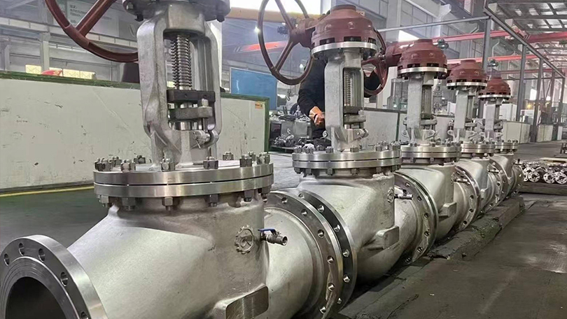
What Is a Globe Valve? Complete Guide to Types, Features, and Applications
Globe valves regulate flow through linear motion of a disc against a stationary seat, making them ideal for throttling, frequent operation, and precise flow control. This guide covers Z-type, Y-pattern, angle, and bellows seal globe valves with selection criteria for pressure, temperature, and media compatibility.
📋 Key Takeaways
- Globe valves regulate flow via linear motion of a disc against a stationary seat, offering precise throttling control.
- Z-type (tee-pattern) provides lowest cost but highest pressure drop; Y-pattern minimizes flow resistance for high-pressure service.
- Angle-pattern globe valves eliminate an elbow fitting, while bellows-seal designs prevent stem leakage in hazardous fluids.
- Needle valves offer fine flow regulation for instrumentation and small-bore applications with tapered disc-to-seat engagement.
Table of Contents
however, This globe valve complete guide covers all major globe valve types including Z-type, Y-type, angle, bellows seal, and needle valves, with working principles, material selection, and sizing information for industrial applications.
additionally, This globe valve complete guide covers all major types, working principles, and selection criteria for industrial applications. A globe valve is a linear motion valve used to regulate or throttle flow in a pipeline. Named for its spherical body shape — though modern designs vary — the globe valve operates using a movable disc (or plug) that seats against a stationary ring seat. By raising or lowering the disc through a handwheel, actuator, or stem, the operator can precisely control the flow rate from fully open to fully closed. Unlike gate valves, which are designed primarily for fully open or fully closed service, globe valves excel at throttling and flow regulation, making them one of the most widely used valve types in industrial piping systems. For a broader overview of how globe valves compare with other valve types, see our comprehensive industrial valve selection guide.
The defining characteristic of a globe valve is the change in flow direction through the valve body. Fluid entering the valve must flow around the seat and disc mechanism, creating a pressure drop that enables precise throttling control. This design inherently produces more resistance to flow than a gate or ball valve of the same size, but delivers superior control accuracy and shutoff capability.
Globe valves are manufactured in sizes from NPS 1/2″ to 48″ and pressure classes from Class 150 to Class 4500, in materials ranging from carbon steel to high-nickel alloys. They are governed by design standards including ASME B16.34, API 602 (for small forged steel valves), and BS 1873 (for flanged steel globe valves).
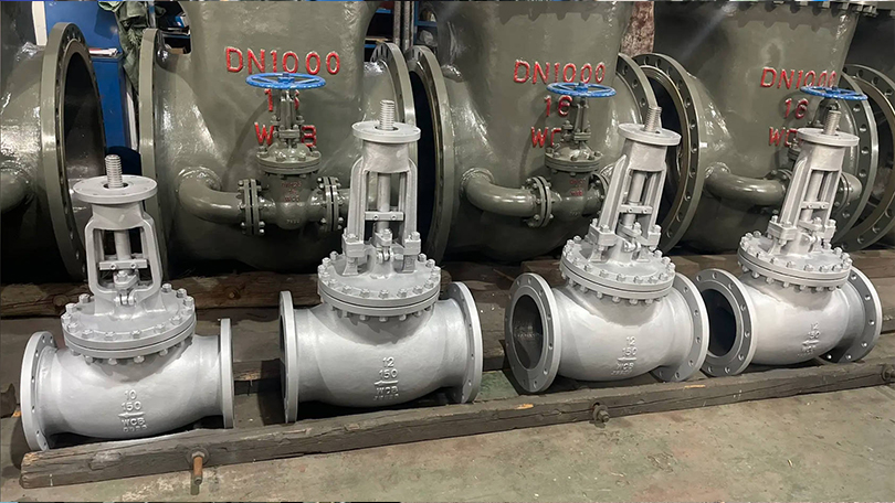
Globe valve types: How Does a Globe Valve Work?
The operating principle of a globe valve is straightforward: a handwheel or actuator rotates the valve stem, which moves the disc (or plug) perpendicular to the seating surface. When the disc lifts away from the seat, flow passes through the annular opening between disc and seat. The distance the disc travels determines the size of this opening and therefore the flow rate.
Key operating characteristics include:
Linear Stem Movement. The stem moves in a straight line (in-and-out) rather than rotating. On rising-stem globe valves, the stem position visually indicates how far the valve is open. Multi-turn actuation is standard — typically 5 to 15 turns from fully closed to fully open depending on valve size and seat design.
Flow Direction. Globe valves are designed for flow under the disc (standard) or over the disc depending on service. In standard installation, flow enters below the disc so that when the valve is partially open, fluid lifts the disc away from the seat. This configuration provides better control during opening. For high-pressure drop services, flow-over-disc installation reduces seat erosion when the valve is nearly closed.
Throttling Precision. The disc-to-seat geometry of a globe valve allows the operator to make fine adjustments to flow. A 1/4-turn of the handwheel on a typical 2″ globe valve changes the flow area by a predictable, repeatable amount. This precision is unmatched by quarter-turn valves (ball, butterfly) in throttling applications.
Globe Valve Complete Guide: Types of Globe Valves
Globe valves are classified by body design, disc design, and bonnet configuration. Each type is optimized for specific pressure, temperature, and flow conditions. The five most common globe valve types are described below.
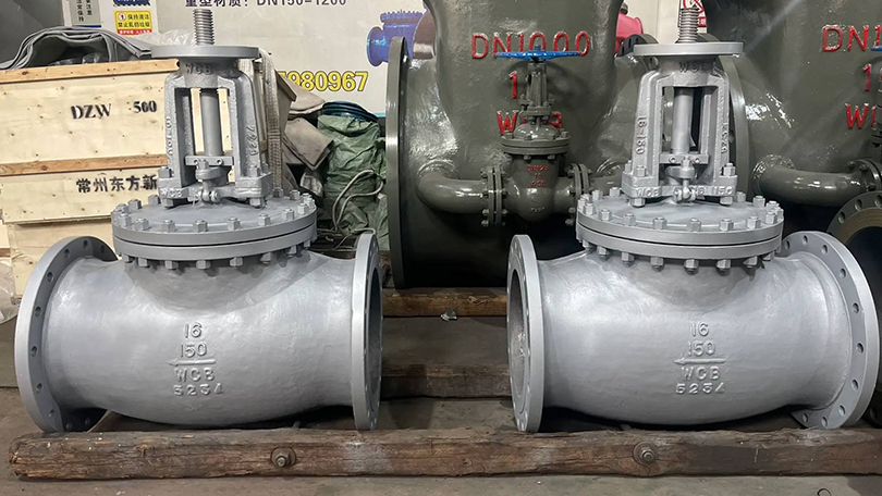
1. Z-Type Globe Valve (Standard Pattern)
The Z-type or standard pattern globe valve features a characteristic Z-shaped flow path. Fluid enters below the disc, makes a 90-degree turn upward through the seat area, then turns another 90 degrees to exit the valve. This configuration creates the highest pressure drop among globe valve designs but also provides the best throttling characteristics. Z-type globe valves are the most common and economical choice for general throttling applications. They are widely used in water, steam, air, and general process services across various industrial applications at pressures up to Class 600 and temperatures up to 425°C. Available in sizes NPS 1/2″ to 24″ with threaded, flanged, or butt-weld end connections.
2. Y-Type Globe Valve (High Pressure)
Y-type globe valves have the seat and stem angled at approximately 45 degrees relative to the pipeline axis (forming a Y shape). This straight-through flow path significantly reduces pressure drop compared to Z-type designs. Y-type globe valves are the preferred choice for high-pressure and high-temperature services, particularly in power generation and steam systems where pressure drop must be minimized. They are commonly specified for boiler feedwater isolation, main steam lines, and turbine bypass applications. The Y-type design also reduces seat erosion in high-velocity services because the flow path is less tortuous. Pressure classes up to Class 4500 and sizes up to NPS 24″ are available.
3. Angle Globe Valve
Angle globe valves combine a globe valve body with a 90-degree turn, serving as both a valve and a pipe fitting. The inlet and outlet are at right angles, eliminating the need for a separate elbow fitting. This design reduces the number of potential leak points, lowers installation cost, and minimizes pressure drop compared to a Z-type globe valve with a separate elbow. Angle globe valves are commonly used in boiler feedwater systems, heater drain applications, and high-pressure let-down stations where space is constrained. They are also preferred for cyclic service where the valve experiences frequent opening and closing, as the angle body reduces thermal and mechanical stress on the piping.
4. Bellows Seal Globe Valve
Bellows seal globe valves incorporate a metal bellows assembly between the stem and the bonnet, creating a leak-tight seal that prevents process fluid from escaping through the stem packing. The bellows are typically made from austenitic stainless steel (AISI 316L or 316Ti) or Inconel alloys and are welded to the stem at one end and the bonnet connection at the other. The primary advantage is zero fugitive emissions — these valves meet the most stringent environmental regulations including TA-Luft (Germany) and EPA Method 21 (USA). Bellows seal globe valves are essential in applications handling toxic, hazardous, flammable, or expensive fluids. They are widely used in chemical processing, pharmaceutical manufacturing, thermal oil systems, heat transfer fluid circuits, and steam systems where stem leakage cannot be tolerated. A secondary backup packing is usually provided above the bellows for added safety.
5. Needle Valve (Small Bore Globe Valve)
Needle valves are small globe valves (typically NPS 1/2″ and smaller) that use a tapered, needle-shaped disc for precise flow regulation. The needle disc fits into a matching conical seat, allowing extremely fine adjustment of the flow orifice. Needle valves are used primarily in instrumentation, sampling systems, chemical injection, and hydraulic control circuits where precise flow metering is required. They are available with threaded, compression, or tube-weld end connections in materials including 316 stainless steel, Monel, and Hastelloy. Maximum operating pressure can exceed 10,000 PSI (Class 6000+) for high-pressure instrumentation applications.
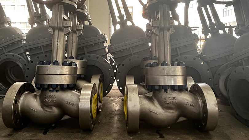
Globe Valve vs. Gate Valve: Key Differences
Gate valves and globe valves are both linear motion valves but are designed for fundamentally different purposes. Understanding the distinctions is critical for proper valve selection.
| Characteristic | Globe Valve | Gate Valve |
|---|---|---|
| Primary Function | Throttling and flow regulation | Isolation (fully open or fully closed) |
| Flow Path | Tortuous (changes direction inside body) | Straight-through (full bore) |
| Pressure Drop | Moderate to high (10-30% of inlet pressure) | Very low (nearly zero when fully open) |
| Throttling Capability | Excellent — precise control at any position | Poor — causes seat erosion if used for throttling |
| Shutoff Tightness | Very good — suitable for bubble-tight shutoff | Excellent — wedge gate design provides tight seal |
| Operating Speed | Multi-turn (5-15 turns depending on size) | Multi-turn (10-30 turns depending on size) |
| Flow Capacity (Cv) | Lower for same pipe size | Higher for same pipe size |
| Water Hammer Risk | Lower — gradual closure characteristics | Higher — can trap fluid in gate cavity |
| Seat Erosion | Moderate — flow impinges on seat | High (when partially open) — wire drawing on seat |
| Typical Cost | Moderate (more complex body casting) | Lower (simpler body design) |
| Preferred Service | Control, regulation, frequent cycling | Isolation, infrequent operation |
The rule of thumb in valve selection: if the application requires flow control or throttling, choose a globe valve. If the application requires isolation with minimal pressure drop, choose a gate valve. Attempting to use a gate valve for throttling will quickly erode the seating surfaces, leading to leakage and premature failure.
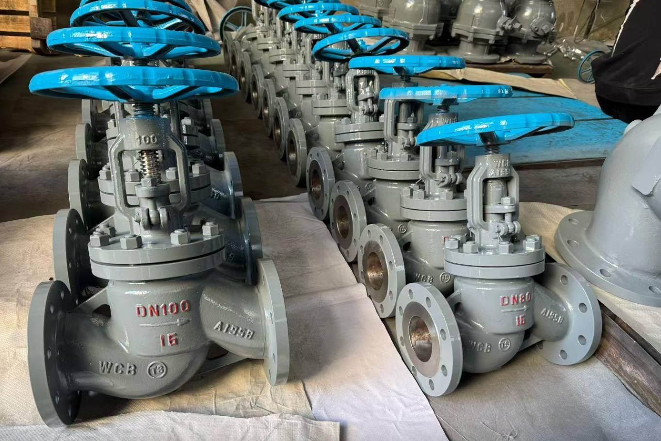
Applications by Industry
Globe valves are used across virtually every industrial sector that handles pressurized fluids. Their throttling capability and reliable shutoff make them indispensable in the following industries:
Oil and Gas. In upstream production, globe valves regulate flow from wellheads, control injection rates for waterflood and gas lift operations, and provide precision flow control in gathering systems. In midstream pipelines, they serve as control valves at pump stations and metering skids. In downstream refineries, globe valves are used for process control on crude distillation units, catalytic crackers, hydrotreaters, and product blending systems. Materials typically include WCB carbon steel for sweet service and CF8M stainless steel or WC6 alloy steel for sour and elevated-temperature services.
Power Generation. Power plants are the single largest application for high-pressure globe valves, particularly Y-type and angle designs. Globe valves control boiler feedwater flow, regulate steam extraction from turbines, provide condensate system control, and serve as turbine bypass valves. The ability to withstand high temperatures (up to 600°C) and pressures (up to Class 4500) makes Y-type globe valves standard equipment in supercritical and ultra-supercritical power plants.
Chemical and Petrochemical. Chemical processing requires precise flow control of reactants, catalysts, and intermediates. Globe valves with bellows seals are used extensively for toxic and hazardous chemicals. Needle valves provide fine metering for catalyst injection and additive dosing. Materials of construction range from 316L stainless steel for general chemical service to Hastelloy C276 and Monel for highly corrosive media such as hydrochloric acid, wet chlorine, and seawater.
Water and Wastewater. Municipal water treatment plants use globe valves for filter backwash control, chemical dosing (chlorine, fluoride, coagulants), and flow regulation in distribution systems. Wastewater treatment plants use globe valves for sludge handling, aeration control, and digester gas systems. Sizes typically range from NPS 2″ to 24″ in Class 150 and Class 300.
HVAC and Building Services. Globe valves are standard equipment in heating, ventilation, and air conditioning systems for controlling hot water, chilled water, and steam flow to coils, radiators, and heat exchangers. Their throttling precision makes them ideal for temperature control in large commercial buildings, hospitals, and data centers.
Pharmaceutical and Food Processing. In pharmaceutical and food-grade applications, globe valves with sanitary connections (clamp ends) and electropolished internal surfaces meet FDA and cGMP requirements for clean-in-place (CIP) and sterilize-in-place (SIP) operations. Materials are typically 316L stainless steel with PTFE or EPDM seat seals.
Material Selection for Globe Valves
The choice of body, bonnet, and trim materials for a globe valve is driven by operating conditions and fluid compatibility. The table below provides a selection guide for common globe valve materials per ASME B16.34 standards.
| Material Grade | ASTM Spec | Max Temperature | Best For |
|---|---|---|---|
| WCB (Carbon Steel) | A216 | 425°C (800°F) | Water, oil, gas, steam — general purpose |
| WCC (Carbon Steel) | A216 | 425°C (800°F) | Lower temperature services, better weldability than WCB |
| CF8 (304 SS) | A351 | 425°C (800°F) | Corrosive media, food processing, nitric acid |
| CF8M (316 SS) | A351 | 425°C (800°F) | Marine, chemical, chloride-containing services |
| WC6 (1.25Cr-0.5Mo) | A217 | 540°C (1000°F) | Steam, high-temperature hydrocarbon processing |
| WC9 (2.25Cr-1Mo) | A217 | 595°C (1100°F) | High-temperature steam, hydrogen service, creep-resistant |
| LCB (Low-temp Carbon) | A352 | −46°C (−50°F) | Cryogenic and cold-weather applications |
| LC3 (3.5% Nickel) | A352 | −101°C (−150°F) | Low-temperature natural gas processing |
Trim Material Guidelines: For standard water and steam service at moderate temperatures, 13% chromium stainless steel (13Cr, A276 Type 410) is the standard disc and seat material. For corrosive services, specify 316 stainless steel trim. For high-temperature or high-velocity services where seat erosion is a concern, Stellite 6 (cobalt-based alloy) hardfacing on both the disc and seat ring provides superior wear resistance. For sour gas services per NACE MR0175/ISO 15156, trim materials must be limited to 22 HRC maximum hardness.
Installation Best Practices
Proper installation is essential for achieving the rated performance and service life of a globe valve. The following best practices should be observed:
Flow Direction. Globe valves have a marked flow direction arrow on the body. Most standard globe valves are designed for flow under the disc — the pressure lifts the disc away from the seat during opening, reducing operating torque. Installing a globe valve backward can cause the disc to lift off the seat under high pressure differentials, leading to loss of control and potential seat damage.
Orientation. Globe valves should be installed with the stem vertical or nearly vertical. For high-temperature steam applications (>400°C), the stem should be in the vertical position to prevent thermal binding and uneven thermal expansion of internal components. For horizontal pipelines, stem-up installation is standard, with the bonnet accessible for maintenance.
Pipe Support. Globe valves are heavier than equivalent gate or ball valves due to the thicker body walls and internal baffle. Ensure adequate pipe supports are installed on both sides of the valve to prevent excessive stress on the body and flange connections. For valves NPS 8″ and larger, consider independent valve supports rather than relying solely on pipe hangers.
Allow for Thermal Expansion. In high-temperature services (>300°C), thermal expansion of the piping system can impose additional stress on the valve end connections. Use flexible expansion joints or loops where necessary, and ensure flanged connections have adequate bolt stretch to maintain gasket compression at operating temperature.
Stem Protection. Globe valve stems are exposed and can be damaged during installation. Protect the stem from impact, weld spatter, and construction debris. Do not use the handwheel or actuator as a lifting point — use the designated lifting lugs or body sling points.
Gasket Selection. For flanged globe valves, select gasket materials compatible with the operating temperature and fluid. Spiral-wound gaskets with 316SS windings and flexible graphite filler are standard for most industrial services. For high-temperature steam, use spiral-wound gaskets with heat-treated filler rings. For low-temperature or cryogenic service, PTFE envelope gaskets may be preferred.
Selection Criteria for Globe Valves
Selecting the right globe valve requires systematic evaluation of the following factors:
1. Service Conditions. Determine the operating pressure, temperature, and fluid characteristics (clean, dirty, corrosive, viscous, hazardous). These parameters define the pressure class, body material, and trim requirements.
2. Flow Control Requirements. Evaluate the required Cv (flow coefficient), turndown ratio, and control characteristics. For applications requiring a wide range of flow rates (turndown > 10:1), specify a globe valve with a characterized disc (equal percentage or linear) or a cage-guided design for precise flow curve matching.
3. Shutoff Class. Globe valves are available with metal seats (Class IV per FCI 70-2 / ANSI/FCI 70.2) and soft seats (Class VI). Specify Class IV for general steam and high-temperature service. Specify soft-seat (PTFE or PEEK) Class VI for bubble-tight shutoff in gas, chemical, or fugitive-emission-sensitive applications.
4. End Connections. Flanged (RF or RTJ per ASME B16.5) for general service up to Class 2500. Butt-weld ends per ASME B16.25 for high-pressure, high-temperature service where flanged connections are not preferred. Threaded ends (NPT) for small-bore valves NPS 2″ and smaller. Socket-weld ends for small-bore, high-pressure service.
5. Actuation. Choose manual handwheel for infrequent operation and throttling. Choose gear-operated handwheel for valves NPS 8″ and larger or when operating torque exceeds 150 Nm. Choose pneumatic actuation for remote control and automated process systems. Choose electric actuation for precise positioning in SCADA-controlled facilities.
6. Fugitive Emission Requirements. For applications handling toxic, hazardous, or volatile fluids, specify bellows seal globe valves or valves with low-emission packing (graphite or PTFE chevron rings) meeting TA-Luft or ISO 15848-1 requirements.
Globe Valve Class 300 Selection Guide
Class 300 globe valves are the most commonly specified pressure class for industrial globe valve applications. Rated at 740 PSI (5.1 MPa) at 100°F per ASME B16.34, Class 300 globe valves offer an optimal balance of pressure capability, cost, and availability for the majority of process, power, and general industrial applications.
Class 300 Globe Valve Specifications at a Glance
| Specification | Class 300 Globe Valve |
|---|---|
| Pressure Rating @ 100°F | 740 PSI (5.1 MPa) — ASME B16.34 |
| Size Range | NPS 1/2″ — 24″ (DN 15 — 600) |
| Body Materials | WCB (A216), WC6 (A217), CF8M (A351), LCB (A352) |
| Bonnet Design | Bolted bonnet, pressure seal bonnet (high-temp), welded bonnet (small bore) |
| End Connections | Flanged RF (ASME B16.5), Butt-Weld (ASME B16.25), Socket-Weld, Threaded |
| Design Standard | BS 1873, ASME B16.34, API 602 (forged small bore) |
| Trim Options | 13Cr (A276 410), 316 SS, Stellite 6 hardfaced seat & disc |
| Operation | Handwheel, gearbox, pneumatic actuator, electric actuator |
| Test Standard | API 598 (hydrostatic shell, seat, backseat tests) |
| Leakage Class | Class IV (metal seat) or Class VI (soft seat) per FCI 70.2 |
Class 300 Globe Valve Selection by Service
| Service Condition | Recommended Type | Body Material | Trim |
|---|---|---|---|
| Water, air & general utility | Z-Type Globe Valve | WCB (A216 Gr. WCB) | 13Cr / F6a |
| Steam up to 425°C | Z-Type or Y-Type | WCB or WC6 | 13Cr + Stellite 6 seat |
| High-pressure steam >425°C | Y-Type Globe Valve | WC9 (A217 Gr. WC9) | Stellite 6 seat & disc |
| Hydrocarbon / refined oil | Z-Type Globe Valve | WCB or LCB | 13Cr / 316 SS overlay |
| Corrosive chemicals | Z-Type Bellows Seal | CF8M (A351 Gr. CF8M) | 316 SS / Alloy 20 |
| HVAC / building services | Z-Type Globe Valve | WCB / Ductile Iron | 13Cr or PTFE soft seat |
| Toxic / hazardous fluids | Bellows Seal Globe Valve | WCB or CF8M | 316 SS + Stellite seat |
| Instrumentation / metering | Needle Valve | 316 SS (A479) | 316 SS / Stellite tip |
Class 300 is the most widely specified pressure class for globe valves across refining, petrochemical, power generation, and general industrial applications. When selecting, confirm that the body material is suitable for the minimum design temperature (MDMT) and that the trim materials are compatible with the process fluid chemistry. For services involving thermal cycling (frequent start/stop), Y-type and angle globe valves provide superior resistance to thermal fatigue compared to Z-type designs.
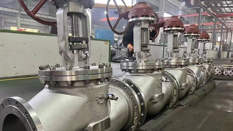
Conclusion
Globe valves are essential flow control components in virtually every industrial fluid handling system. Their ability to provide precise, repeatable throttling — combined with reliable shutoff capability — makes them the valve of choice when control matters more than conductance. The five main types — Z-type standard, Y-type high-pressure, angle globe, bellows seal, and needle valve — cover the full spectrum of industrial applications from low-pressure HVAC circuits to supercritical power plant steam lines.
When selecting a globe valve, the primary decision criteria are: operating pressure and temperature (determining the Class and body material), throttling precision requirements (determining the disc and seat design), fluid compatibility (determining trim materials and seal type), and end connection compatibility with the existing piping system. The Class 300 selection guide provided in this article serves as a practical reference for the most common industrial globe valve applications.
Vornet Valve manufactures a comprehensive range of globe valves in carbon steel (WCB, WCC, LCB), stainless steel (CF8, CF8M, CF3M), and alloy steel (WC6, WC9), with sizes from NPS 1/2″ to 24″ and pressure classes from Class 150 to Class 2500. All Vornet globe valves are designed, manufactured, and tested in accordance with BS 1873, ASME B16.34, API 602, and API 598 standards, ensuring reliable performance in the most demanding industrial services.
Frequently Asked Questions
Q1: What is the main difference between a globe valve and a gate valve?
A globe valve is designed for throttling and flow regulation, using a disc that moves perpendicular to the seat to precisely control flow. A gate valve is designed for isolation (fully open or fully closed), using a wedge that slides in and out of the flow path. Globe valves create a significant pressure drop but offer excellent control; gate valves have minimal pressure drop when fully open but must not be used for throttling as it causes seat erosion and leakage.
Q2: Why is it called a globe valve?
The name comes from the original body design, which featured a spherical (globe-shaped) central chamber that housed the seat and disc mechanism. While modern globe valves may have different exterior shapes, the internal structure — a baffle with a circular seat that creates a change in flow direction — retains the globe valve name. The spherical body shape provided optimal pressure containment for the disc and seat assembly.
Q3: Can a globe valve be used for isolation (on/off) service?
Yes, globe valves can be used for isolation service and provide very good shutoff, particularly with soft seats that achieve bubble-tight Class VI shutoff. However, for applications where the valve is rarely operated and minimum pressure drop is required, a gate valve is the better choice. For applications that require both throttling and positive shutoff in the same valve — such as bypass circuits and control stations — a globe valve is the appropriate selection.
Q4: What does the pressure drop across a globe valve depend on?
The pressure drop across a globe valve depends on the valve size (flow area), the disc position (how far open the valve is), the flow rate (GPM or LPM), and the specific gravity of the fluid. For a fully open globe valve, the pressure drop is typically 10-30% of the inlet pressure, compared to 1-3% for a fully open gate valve. The Cv (flow coefficient) published by the manufacturer is used to calculate the exact pressure drop at a given flow rate using the formula: ΔP = SG × (Q / Cv)², where Q is flow rate and SG is specific gravity.
Q5: What is the maximum operating temperature for globe valves?
The maximum temperature depends on the body material and seat type. Standard carbon steel (WCB) globe valves are rated to 425°C (800°F). Alloy steel WC6 (1.25Cr-0.5Mo) extends this to 540°C (1000°F). Alloy steel WC9 (2.25Cr-1Mo) reaches 595°C (1100°F). For metal-seated globe valves with Stellite hardfacing, continuous operation at 595°C is achievable. For services above 595°C, special high-temperature alloys such as Inconel 625 or AISI 310 stainless steel are required, and valve design must account for reduced material strength at elevated temperatures per ASME B16.34 derating curves. All material specifications reference ASTM International standards.
Q6: How do I select between a Z-type and a Y-type globe valve?
Select a Z-type globe valve for general throttling applications where some pressure drop is acceptable and cost is a primary consideration. Select a Y-type globe valve for high-pressure (>Class 600) or high-temperature (>400°C) applications where pressure drop must be minimized, particularly in boiler feedwater, main steam, and turbine bypass systems. Y-type globe valves cost approximately 20-40% more than equivalent Z-type valves but offer 30-50% lower pressure drop and significantly better resistance to thermal fatigue and seat erosion in severe service conditions.
Q7: When should I specify a bellows seal globe valve?
Specify a bellows seal globe valve whenever the process fluid is toxic, flammable, hazardous, expensive, or environmentally regulated. Bellows seal globe valves are mandatory in many jurisdictions for applications handling benzene, hydrogen sulfide, chlorine, phosgene, thermal oil (heat transfer fluids), and other fugitive-emission-sensitive media. They are also recommended for steam systems where stem leakage would cause safety hazards or energy losses. Bellows seal valves meet TA-Luft and EPA Method 21 fugitive emission standards and provide zero measurable leakage from the stem seal for the life of the bellows (typically 10,000+ cycles).
Q8: What maintenance is required for globe valves in industrial service?
Routine maintenance includes: (1) Periodic stem seal adjustment — tighten packing nuts gradually as the packing wears, but avoid over-tightening which increases operating torque; (2) Seat leak testing — perform during each plant turnaround to verify shutoff integrity; (3) Disc and seat ring inspection — check for pitting, galling, wire drawing, and erosion, particularly on the downstream seat face; (4) Stem thread lubrication — apply high-temperature anti-seize lubricant to stem threads annually; (5) Bellows integrity testing — for bellows seal valves, perform a pressure test on the bellows chamber at each turnaround; (6) Gasket replacement — replace bonnet gasket whenever the valve is disassembled for internal inspection. For severe service applications (high-temperature steam, erosive fluids), inspection frequency should be increased to every 6-12 months.
For inquiries about globe valve selection, technical quotation, custom manufacturing, or bulk procurement of Class 150 to Class 2500 globe valves, contact our engineering team.
Need a Globe Valve for Your Application?
Vornet Valve manufactures a comprehensive range of globe valves in carbon steel, stainless steel, and alloy steel — Z-type, Y-type, angle, bellows seal, and needle valves — from Class 150 to Class 2500, NPS 1/2″ to 24″. All designed to BS 1873, ASME B16.34, and API 602 standards.
• Globe Valve Selection Guide
• API 600 Gate Valve vs Globe Valve
• Control Valve Selection Guide
Vornet Valve is a China-based industrial valve manufacturer with over 20 years of experience. We manufacture globe valves to BS 1873, ASME B16.34, and API 602 standards — including Z-type, Y-pattern, angle, bellows seal, and needle globe valves. Available in sizes NPS 1/2″ to 24″, Class 150 to Class 2500, with materials from WCB carbon steel to Hastelloy C276. Our globe valves are used in oil & gas, power generation, chemical processing, and water treatment applications worldwide.
Contact us today for a quote or technical consultation:
- Email: jessamyn@vornetvalve.com
- WhatsApp: +86 17888190118
- Website: www.vornetvalve.com