
3-Way Ball Valve Applications: L-Port, T-Port & Selection
📋 Key Takeaways
- Use the manufacturer’s port diagram: L-port, T-port, common-port location, seat arrangement and transition paths vary by model.
- A three-way switching valve does not automatically provide mixing-ratio control or positive isolation throughout travel.
- Pressure class, capacity, temperature, shutoff and actuator torque must be verified for each port path and operating case.
- Critical routing may still require check valves, independent block valves, interlocks and position feedback.
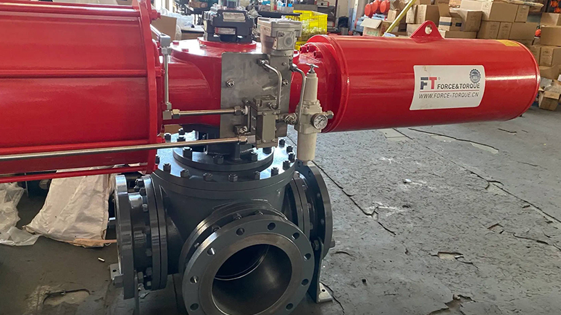
A three-way ball valve routes flow among three connections through an L-, T- or manufacturer-specific drilled ball. It can simplify switching, diverting or combining service, but the port diagram, seat arrangement and permitted operating positions—not the label “L-port” or “T-port” alone—determine which paths are open, blocked or briefly connected during travel.
Read the Manufacturer’s Flow Diagram First
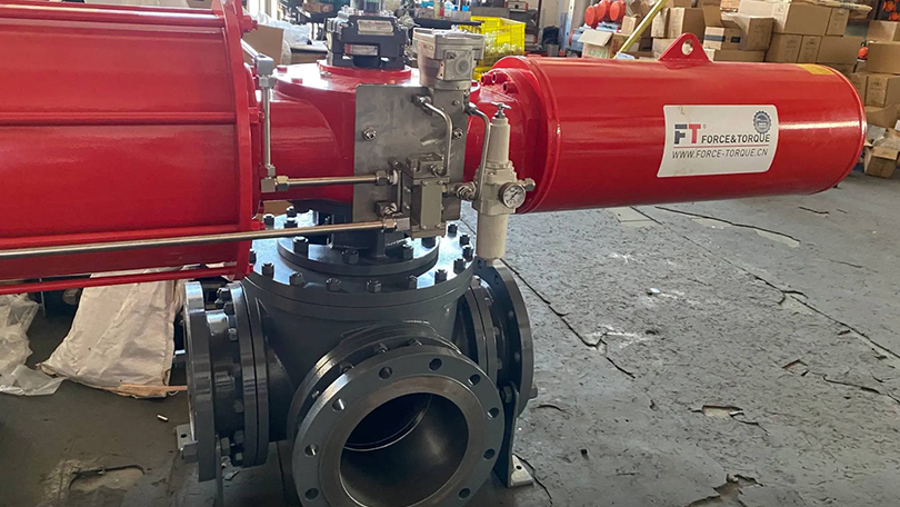
Port letters such as A, B, C or AB are not universal. The common port may be on the side or bottom, and handle position does not always show the internal path intuitively. Put the approved port diagram, normal position, alternate position and fail position on the valve datasheet and piping drawing.
| Ball pattern | Common capability | What must be verified |
|---|---|---|
| L-port | Usually connects the common port to one of two adjacent branches | Which port is common, available 90°/180° positions, overlap or shutoff during travel, and seat arrangement |
| T-port | Can provide selected two-port paths and, in a stated position, connect all three ports | Exact drilled geometry, which two-port paths are available, whether any position closes all ports, and unused-branch isolation |
| Special pattern | Crossover, bottom-entry, sampling or manufacturer-specific switching | Use only the supplied flow diagram and position table; do not infer from generic L/T sketches |
An L-port does not guarantee that two process sources remain positively isolated during every part of rotation. A T-port does not necessarily leave the unused branch partially open. Ball geometry, number/location of seats and travel stops control the actual result.
Mixing, Diverting and Source Selection
Diverting one inlet to two possible outlets
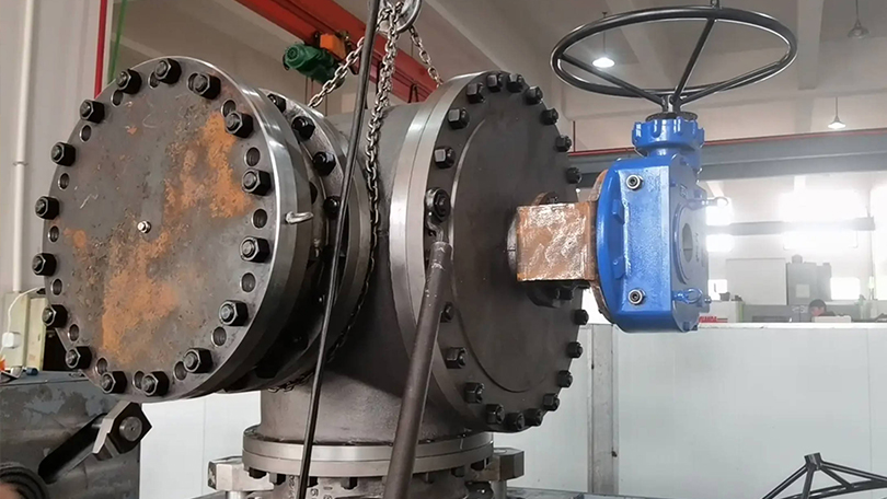
An L-port is commonly selected when one common inlet must connect to either branch. A T-port may be usable when its diagram provides the required paths or an intentional all-ports-open position. Define whether momentary overlap, momentary shutoff or continuous flow during transfer is acceptable.
Selecting one of two sources
The same routing can be reversed only if process hydraulics, pressure direction, backflow and valve construction permit it. If cross-contamination or reverse flow is hazardous, do not rely on the three-way valve alone; evaluate check valves, independent block valves, double isolation, interlocks or a validated switching sequence.
Combining two streams
A T-port can join two inlet streams to one outlet, but a standard on/off ball valve does not regulate the mixing ratio. Flow split depends on upstream pressures, branch resistance, fluid properties and downstream conditions. Proportional temperature or composition control requires a characterized control-grade valve and a sizing/control review.
Transitions Can Matter More Than End Positions
During rotation, the drilled passage can momentarily connect, throttle or close ports. For incompatible chemicals, hot/cold streams, pressure boundaries or relief systems, the transition path can create a hazardous cross-connection or deadhead. Require the manufacturer’s intermediate-position diagram when continuity or isolation matters.
Multi-position valves may need 90°, 180° or special-angle actuators and positive travel stops. Do not assume a standard quarter-turn actuator provides every required position.
Shutoff and Seat Arrangements
Three-way ball valves may use two, three or four seats, and not every port is necessarily pressure-rated or sealed identically in every direction. Specify:
- pressure direction and differential for each operating position;
- which ports require tight shutoff and the allowable leakage;
- whether cavity or blocked-port pressure can become trapped;
- seat relief or venting direction and thermal-expansion protection;
- fire-safe, emissions or antistatic qualification when applicable.
“Positive isolation” must be tied to a stated test standard, pressure, direction, medium and acceptance criterion. A flow-pattern drawing alone is not leakage evidence.
Pressure Class Is Not a Fixed PSI Value
ASME Class 150 or another Class designation does not equal one universal working pressure. Determine allowable pressure at the coincident metal temperature from the applicable material group and construction standard. Seats, seals, packing, body joints, end connections and actuators can impose lower limits.
Do not publish universal temperature ceilings for PTFE, reinforced PTFE, PEEK or metal seats. Polymer compound, fillers, pressure, chemistry, thermal cycling, ball finish and manufacturer qualification all affect the envelope. A metal seat also does not automatically establish fire-safe performance; require the applicable type-test report.
Capacity and Pressure Drop
Three-way capacity depends on port pattern, selected path and body geometry. Straight-through and 90-degree paths can have different Cv/Kv values. “Full port” does not mean that a three-way valve has the same capacity as a two-way valve of equal nominal size.
- Calculate the required Cv/Kv for each path and operating case.
- Use the manufacturer’s tested coefficient for that exact port position.
- Check branch pressure balance, velocities, cavitation/flashing for liquids and choking/noise for gases.
- For combining service, analyze interaction between both inlet branches.
- Confirm stable actuator positioning if the valve will modulate rather than switch.
Materials and Process Compatibility
Specify body, ball, stem, seats, seals, packing, bolting and any cavity filler separately. A WCB, CF8M or other body grade does not establish compatibility for the complete valve. Review corrosion, erosion, solvent swelling, permeation, rapid gas decompression, solids, cleaning chemicals and galvanic effects.
For abrasive or solids-bearing media, ordinary soft-seat three-way valves may suffer seat damage or cavity accumulation. For severe temperature or slurry service, obtain a model-specific engineered design rather than assuming a metal seat or hardfacing solves every mechanism.
Application Guidance
| Application | Appropriate engineering checks |
|---|---|
| Filter or heat-exchanger changeover | Continuous-flow requirement, transition overlap, independent isolation for maintenance and pressure equalization |
| Primary / standby pump selection | Backflow, pump deadhead, check valves, interlocks, common-mode failure and maintenance isolation |
| Chemical routing or blending | Cross-contamination, reaction hazard, flush/dead-leg volume, materials and transition path |
| HVAC mixing/diverting | Installed flow characteristic, authority, pump arrangement, control signal and minimum circuit flow |
| Hygienic / bioprocess | Applicable ASME BPE/project requirements, drainability, surface finish, cavity filling, cleanability, sterilization and documentation |
| Steam or high-energy service | Specialized pressure-temperature design, thermal relief, erosion, condensate, actuation and governing plant standard |
Generic three-way ball valves should not be advertised as suitable for WFI, SIP, hydrogen generator cooling, high-pressure feedwater or another critical service without the exact design qualification.
One Three-Way Valve vs Multiple Two-Way Valves
| Decision factor | Single three-way valve | Multiple two-way valves |
|---|---|---|
| Footprint and actuation | Can reduce components and coordinate paths mechanically | More valves/actuators but flexible layout |
| Isolation for maintenance | One body can be a common-mode failure; separate blocks may still be needed | Individual branches can be independently isolated when designed accordingly |
| Transition behavior | Defined by one ball pattern and actuator sequence | Defined by interlocks and valve timing; sequencing errors must be controlled |
| Availability | Size, pressure, material and special trim options may be limited by model | Broader standard-valve choices in some services |
| Cost | Compare installed and lifecycle cost for the actual design; no universal percentage saving applies | |
Actuation, Position Feedback and Fail State
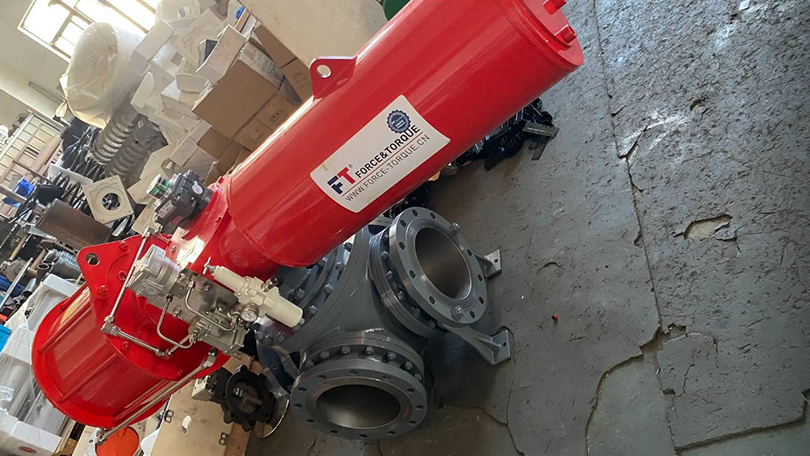
Calculate actuator torque for the maximum differential pressure and minimum/maximum service temperature, including seat friction, stem packing, frequency and design margin. For three-position service, verify the actuator, positioner or stop module can reach and repeat every required angle.
Define the safe state for loss of air, power or signal. A spring-return actuator usually drives to one end position, which may not be the process-safe routing. An accumulator, fail-in-place unit, dual-solenoid logic or independent shutdown valves may be required. Provide independent position feedback for critical routing.
Specification Checklist
- Draw and label all ports; identify common, inlet and outlet paths.
- Provide required end positions and every permitted intermediate position.
- State whether flow must remain continuous or branches must never overlap.
- List pressure-temperature and flow cases for every path and direction.
- Specify shutoff ports, direction, test method and allowable leakage.
- Define material, seat/seal, emissions, fire-safe and cleaning requirements.
- Calculate Cv/Kv and actuator torque for each operating case.
- Define actuator angles, fail state, interlocks and position feedback.
- Request GA, port/seat schematic, P-T curve, Cv/Kv data, torque and test records.
Send the process diagram and operating cases to Vornet’s engineering team for a model-specific three-way valve review.
Frequently Asked Questions
What is the difference between an L-port and a T-port three-way ball valve?
An L-port commonly connects a designated common port to one of two branches. A T-port can provide selected two-port paths and an all-ports-connected position. Exact paths and transitions must be read from the manufacturer’s diagram.
Does an L-port always isolate the unused branch?
Not automatically in every design and throughout travel. Verify the seat arrangement, end-position leakage test and intermediate transition path. Use independent isolation when cross-contamination is hazardous.
Can a T-port ball valve control a mixing ratio?
A standard switching valve only creates the flow path. Mixing ratio depends on both branch pressures and resistances. Proportional control requires a characterized control-grade design and sizing/control analysis.
Does every Class 150 three-way ball valve have the same pressure rating?
No. Class is a rating designation. Allowable pressure depends on material group, coincident temperature, construction standard and all lower component limits.
Does a three-way valve always rotate 90 degrees?
No. Some duties use 90-degree switching, while multi-position patterns can require 180 degrees or special stops. Specify every required angle and port path.
Can one three-way valve replace two or three two-way valves?
Sometimes, but compare transition behavior, maintenance isolation, common-mode failure, availability, interlocks and lifecycle cost. Separate block valves may still be required.
Is a generic three-way ball valve suitable for hygienic or steam service?
Not automatically. Hygienic duties require drainability, cleanability, surface and documentation checks; steam or high-energy duties require a qualified pressure-temperature, seat and thermal-relief design.
What information is needed for a quotation?
Provide the labeled piping diagram, flow paths and transitions, all pressure-temperature-flow cases, fluids, materials, shutoff requirements, Cv/Kv, actuation angles, fail state, interlocks and documentation needs.