Extraction Steam Check Valve Maintenance: Complete Step-by-Step Guide
What Is an Extraction Steam Check Valve?
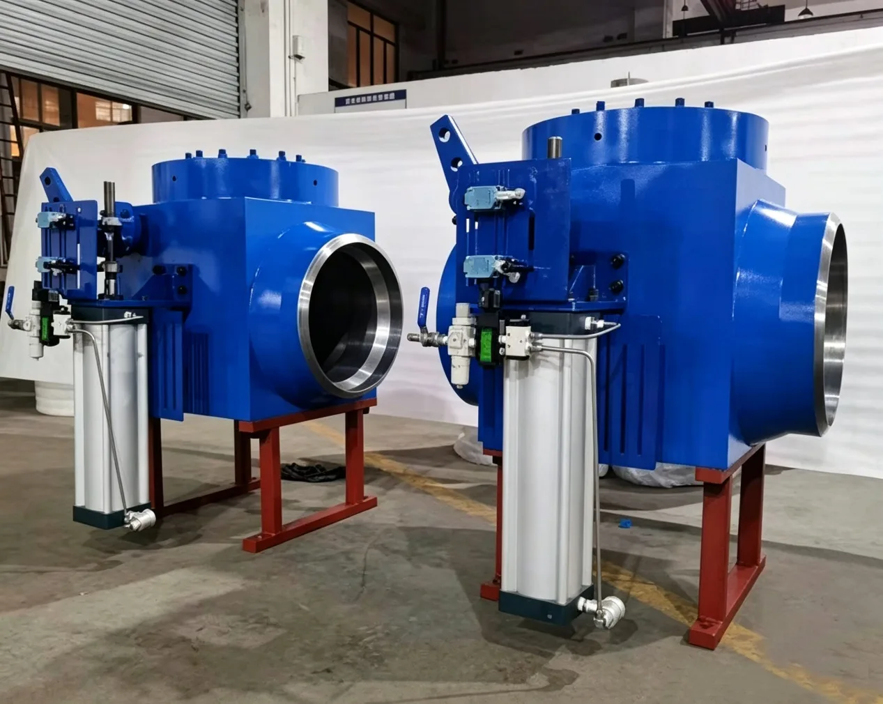
An extraction steam check valve is installed on each extraction steam line of the regenerative feedwater heating system in steam turbine units. Its primary function is to prevent backflow of steam from heaters and pipelines into the turbine during load rejection or emergency shutdown, which could otherwise cause turbine overspeed and serious accidents.
Operating Principle
During startup: The extraction check valve is initially closed. As heaters are started sequentially, the pneumatic actuator receives compressed air, causing the piston rod to rotate the lever arm. This releases the limit on the valve disc shaft, allowing the disc to open freely under extraction steam pressure.
During normal operation: The valve disc remains fully open due to continuous extraction steam pressure acting on it.
During load rejection: When the turbine trips, extraction steam pressure drops rapidly. The valve disc closes quickly under its own weight, preventing steam from flowing back into the turbine and protecting the unit from overspeed.
Preparation Before Maintenance
Before starting maintenance work, ensure the following:
- Equipment is taken out of service and all protection systems, power supplies, and air supplies are isolated
- Disconnect the air inlet and outlet connections of the pneumatic actuator
- Remove the pin connecting the actuator piston rod to the valve lever
- Loosen the actuator mounting bolts and remove the actuator assembly
- Place all removed parts on a clean, organized work surface
1. Valve Disassembly
- Mark alignment between bonnet and valve body with a marker, then remove bonnet bolts and lift off the bonnet.
- Remove the bearing, oil seal ring, and lever from the lever shaft side. Place components in designated locations.
- Loosen the large seal cover nut and remove the large retaining ring.
- After marking alignment, remove the large bracket mounting bolts and lift off the bracket.
- Remove the lever shaft and bushing.
- Remove the small bracket and attachments from the rocker arm shaft side.
- Loosen the retaining nuts on the small retaining ring and remove it.
- After marking alignment, remove the flange cover bolts and lift off the flange cover.
- Remove the rocker arm and valve core assembly.
- Extract the rocker arm and valve core. Place all components in designated clean areas.
2. Cleaning and Inspection
- Seat and disc sealing surfaces: Check for grooves, pitting, or scratches across the sealing surface. Contact must be continuous around the full circumference. Any defects must be repaired by lapping or grinding.
- Disc-to-rocker arm connection: Check the clearance between adjustment shim and rocker arm — it should be 1.0–1.2mm. Verify the lock nut is secure and the tack weld is intact with no cracks.
- Shaft and bushing clearances: Verify clearances between lever shaft, rocker arm shaft, and their respective bushings meet specifications. All surfaces should be smooth and free of pitting.
- Packing: Check packing in the large seal cover and flange cover. Replace if damaged.
- Bonnet and body sealing faces: Inspect for grooves, sand holes, or scratches that could affect sealing.
- Gasket surfaces: Clean and inspect sealing surfaces. Remove all old gasket material.
- Keys and keyways: Clean thoroughly and ensure proper fit.
3. Reassembly
Before reassembly, apply molybdenum disulfide powder to all shaft and bushing surfaces, rubbing vigorously until they shine. Reassemble in reverse order following alignment marks. Key points:
- Adjust shim thickness to ensure disc rotation angle meets manufacturer specifications. Tack-weld the lock nut securely to the disc after adjustment.
- Maintain 1.0–1.2mm clearance between lever shaft/rocker arm shaft and rocker arm ends.
- When tightening, ensure both shafts remain concentric to prevent binding.
- During packing gland tightening, verify both shafts operate freely without binding.
- All gaskets must be replaced with new ones.
4. Actuator Disassembly, Inspection and Reassembly
- Mark alignment between top cover, cylinder body, and base. Remove stud bolts.
- Slowly and alternately loosen the two long stud bolt nuts until fully released.
- Separate top cover, cylinder body, and base. Remove piston, stem, and spring.
- Remove cotter pin and hexagonal slotted nut to separate piston rod from piston.
- Clean and inspect all actuator components. Cylinder inner wall must be smooth. Check spring free length. Piston rod and piston surfaces must be smooth and free of damage.
- Replace all O-rings with new high-temperature resistant seals. Apply silicone grease to cylinder inner wall and piston surface before reassembly.
- After reassembly, test the piston rod stroke with compressed air — motion should be smooth and continuous with no binding.
5. Final Assembly and Overall Verification
Mount the actuator on the valve body and connect to the valve lever. Connect compressed air lines and perform an overall function test:
- The stroke length during compressed air operation must meet manufacturer specifications.
- The entire mechanism should operate smoothly and continuously without binding.
- Verify that the valve position indicator is correctly calibrated. Coordinate with instrumentation and control technicians to check open/close signals match actual valve position.