
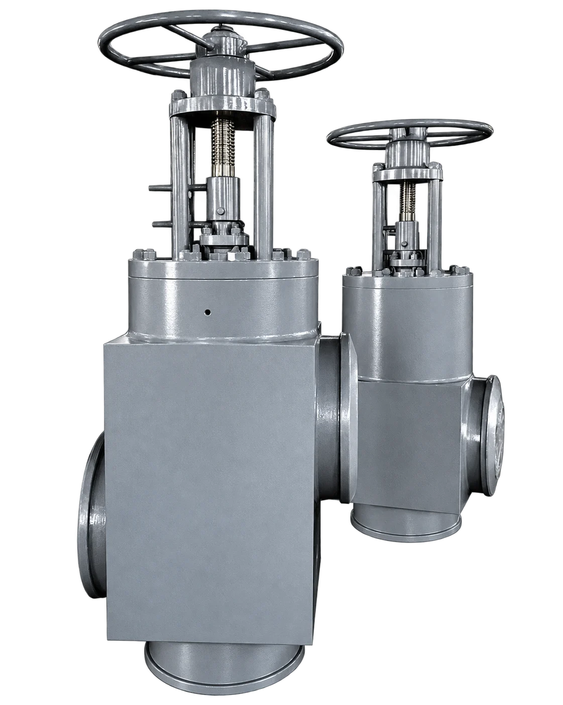
High-Pressure Feedwater Heater Isolation Valves
| Size Range | NPS 6–28 (DN150–DN700) |
|---|---|
| Pressure Rating | Class 1500–2500 (PN200–PN500) |
| Material | Carbon Steel, Alloy Steel, Stainless Steel, WB36 |
| Media | Water, Steam |
| Connection Type | BW |
| Service Temperature | Up to 648 °C |
| Valve Type | Three-Way Valve, Engineered Product, Globe |
Feedwater Heater Isolation Valve System Overview
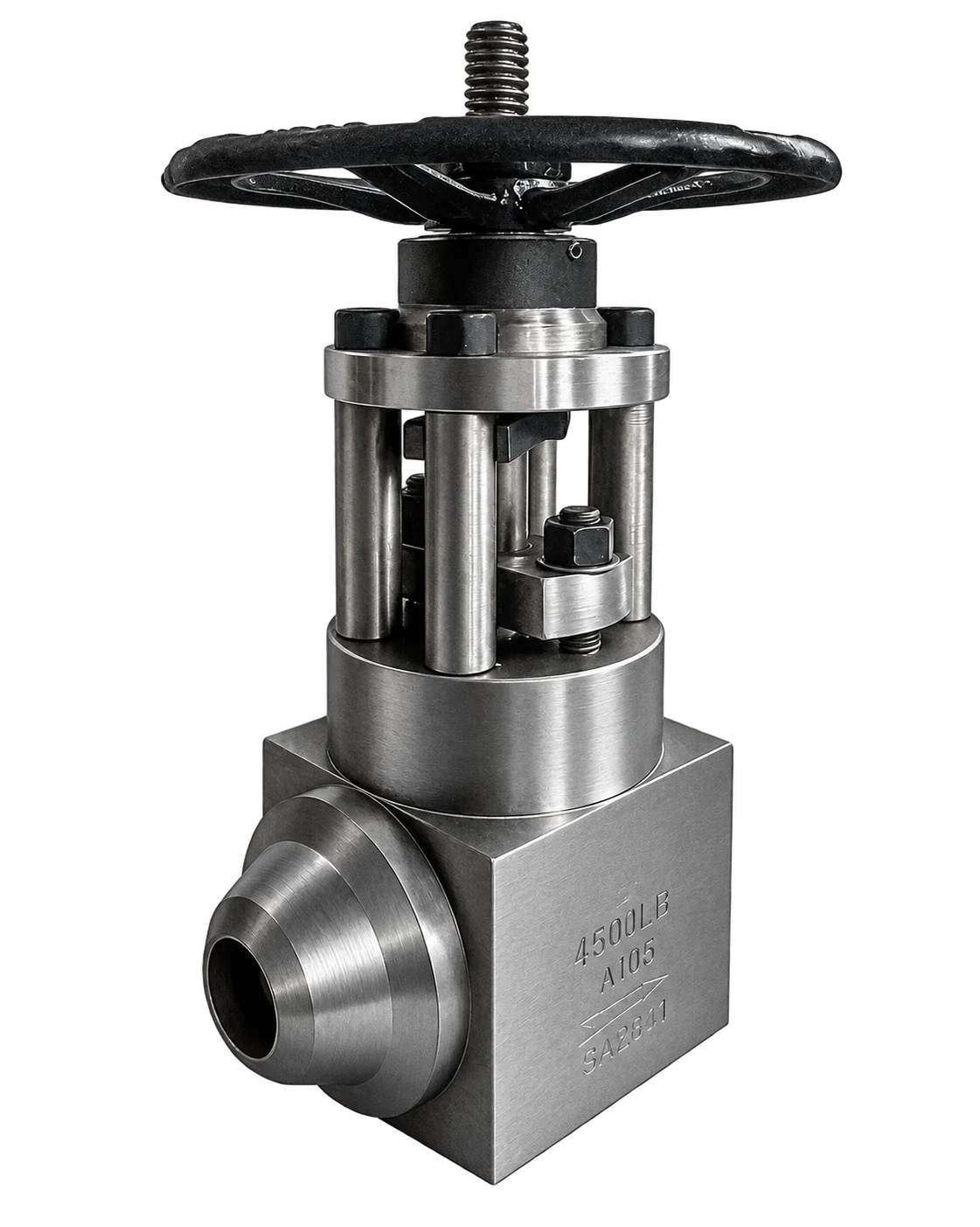
High-pressure feedwater heater isolation valves form a coordinated inlet, outlet and bypass valve system that protects feedwater heaters in thermal power plants. The valves isolate a heater following a tube rupture, high water level or excessive backpressure and redirect feedwater through the bypass path.
Feedwater heater bypass valves use built-in water-hydraulic actuators for fast changeover and fail-safe bypass operation. Their one-piece body and split-stem design support commissioning, maintenance and reliable turbine operation under demanding high-pressure and high-temperature service.
Key Features
- These valves are designed to bypass high-pressure feedwater around a group of heaters in the event of a high-water level in the shell caused by a defective tube, weld or drain system.
- Protection is achieved by installing fast-closing tee and changeover valves in the pipework around a heater or group of heaters.
- One-piece body designs are available for temperatures up to 648°C. The applicable limit for each size, pressure class and material must be confirmed by the approved project datasheet.
- A split stem with a separate coupling allows manual operation for commissioning and maintenance without affecting normal operation.
- The motive power employed is feedwater pressure, and the system is designed to fail safe so that the heaters are bypassed if either the electrical or pneumatic supply fails.
- Protects the feedwater heater steam jacket against rupture and leakage.
- Protects turbine extraction from excessive backpressure.
- Allows the feedwater heater to be isolated without disrupting water circulation through the bypass system.
- Can bypass the feedwater heater during plant start-up and periods of low turbine load.
- Allows the heater to be bypassed at peak loads to increase turbine power output and improve overall plant efficiency.
Related Power Station Valves
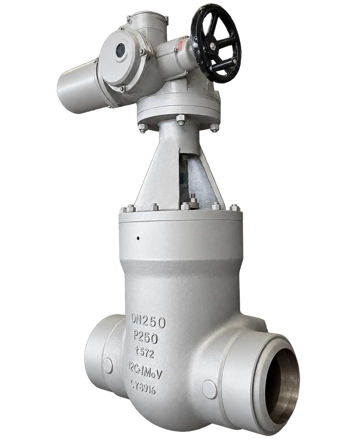
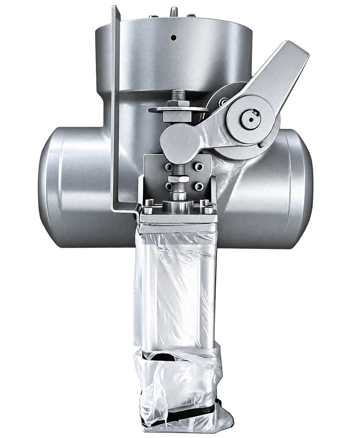
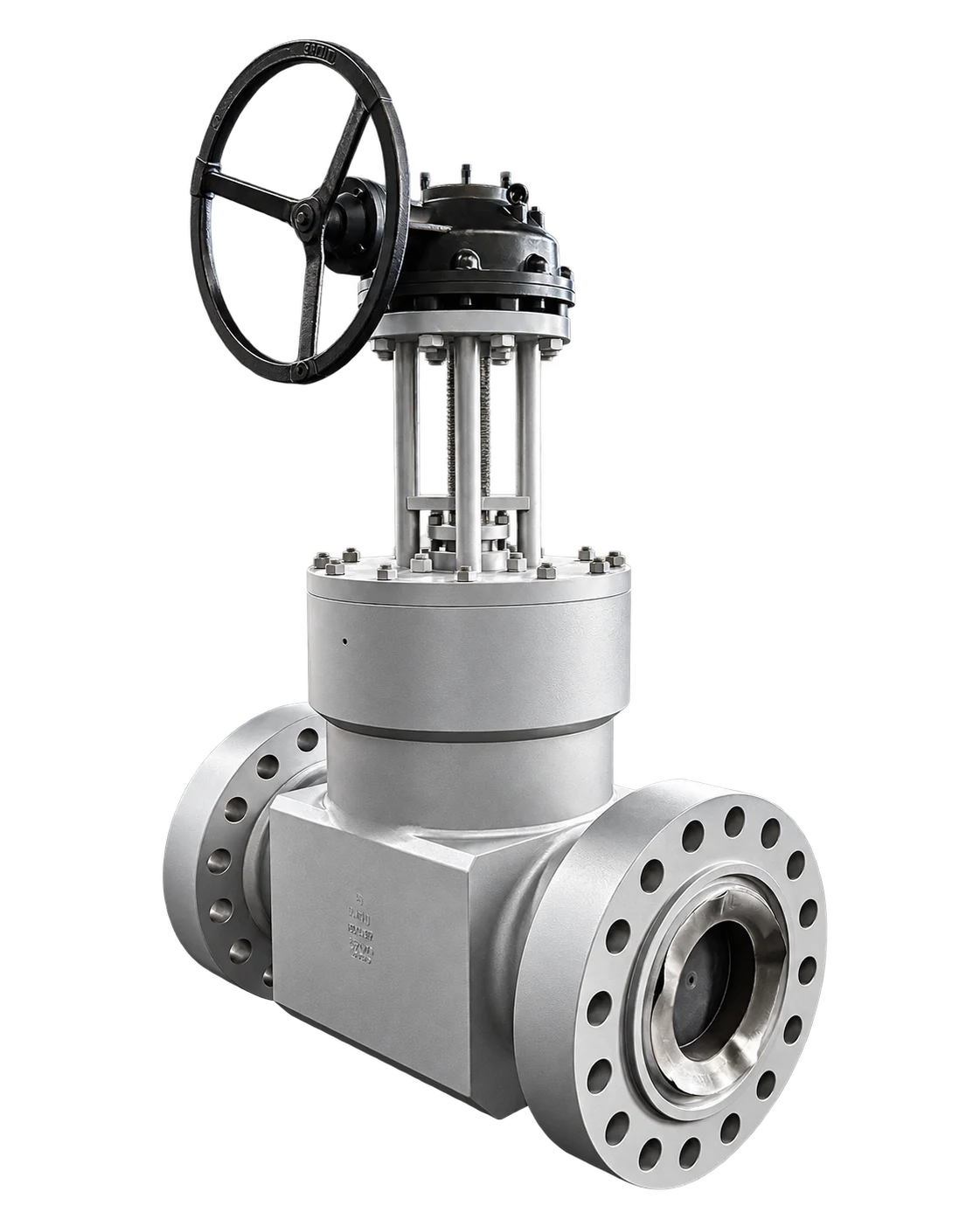
Discuss Your Feedwater Heater Isolation Valve Requirements
Related
Documents
Download product catalogues and practical RFQ tools for high-pressure and power-station valve projects.
Explore All Downloads ↗
Feedwater Heater Isolation Valve FAQ
What is a feedwater heater isolation valve system?
A feedwater heater isolation valve system is a coordinated inlet, outlet and bypass valve arrangement used to isolate a high-pressure feedwater heater while maintaining the required feedwater route to the economizer or boiler.
How do feedwater heater bypass valves protect against tube rupture or high water level?
When a tube rupture, weld failure, drain-system fault or high-water-level trip occurs, the system isolates the affected heater and redirects feedwater through the bypass path. The final trip signal and operating sequence must follow the approved plant control logic.
How do the inlet, outlet and bypass valves work together?
The inlet valve stops feedwater entering the heater, the outlet or changeover valve completes isolation and prevents unwanted reverse flow, and the bypass valve establishes the alternate feedwater path. The exact arrangement is confirmed from the approved piping schematic.
What sizes, pressure classes, materials and temperatures are available?
The published series range is NPS 6–28 (DN150–DN700), Class 1500–2500 (PN200–PN500), with carbon steel, alloy steel, stainless steel and WB36 options, BW ends and service temperatures up to 648 °C. Each size, class, material and temperature combination must be confirmed against the approved datasheet.
How does the water-hydraulic and fail-safe operation work?
Built-in water-hydraulic actuators use feedwater pressure as motive power for changeover. The system is designed to bypass the heater if the electrical or pneumatic control supply fails. A split stem supports manual operation for commissioning and maintenance; final fail position and operating sequence are project-specific.
What information is required for valve selection and quotation?
Provide the heater arrangement and piping schematic, inlet, outlet and bypass sizes, design and operating pressure, temperature, media, flow conditions, material, BW preparation, actuation, control and fail-safe requirements, plus required testing, inspection and documentation.