
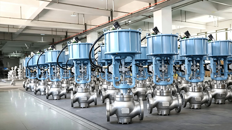
What Is a Control Valve? Complete Guide to Types, Features, and Applications
📋 Key Takeaways
- Control valves modulate fluid flow using an actuator-driven closure element positioned by a controller signal.
- Major control valve types include globe, ball, butterfly, plug, diaphragm, and pinch valves, each with distinct flow characteristics.
- Globe valves offer linear flow characteristics ideal for throttling; ball and butterfly valves suit on-off and modulating services.
- Proper actuator sizing, positioner calibration, and flow coefficient (Cv) selection are essential for accurate loop control.
Control valve types — globe, rotary ball, butterfly, cage-guided, and diaphragm — how actuators and positioners work, flow characteristics (linear, equal percentage, quick opening), critical selection criteria including Cv, pressure drop, and noise control, plus a complete Class 300 selection guide with actuator sizing tables. This guide covers everything from basic control valve principles to advanced applications across oil and gas, power generation, chemical, water, pharmaceutical, and food industries.
This control valve selection guide covers types, sizing, actuators, positioners, and applications for industrial process control. A control valve is a power-operated device used to regulate the flow rate, pressure, temperature, or level of a process fluid by varying the size of the flow passage as directed by a control system signal. Unlike manual valves that require a human operator to turn a handwheel, a control valve receives an electronic or pneumatic signal from a process controller and automatically positions its internal throttling element — such as a plug, ball, or disc — to maintain the desired process variable at its setpoint.
Control valves are the final control element in nearly every industrial process loop. They work in conjunction with sensors (transmitters) that measure the process variable and controllers (PLCs, DCS, or standalone PID controllers) that compare the measured value to the setpoint and generate an output signal. The control valve receives this signal through its actuator and positioner, adjusts its opening position accordingly, and thereby influences the process condition to match the setpoint. This closed-loop control architecture forms the foundation of modern industrial automation.
The global control valve market was valued at approximately USD 8.5 billion in 2025 and is projected to exceed USD 12 billion by 2032, driven by increasing automation in oil and gas, power generation, chemical processing, water treatment, and pharmaceutical manufacturing. Ultimately, Control valves are manufactured in sizes from NPS 1/2″ to 48″ and pressure classes from Class 150 to Class 4500, in materials ranging from cast carbon steel to exotic alloys such as Hastelloy, Monel, and Inconel. Design, testing, and performance criteria are governed by international standards including IEC 60534, ISA 75.01, ASME B16.34, and API 598.
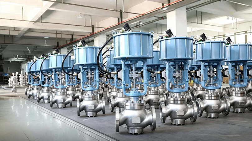
How Does a Control Valve Work? — Control Valve Types
A control valve operates through the coordinated action of three primary subsystems: the valve body (which contains the flow-controlling element), the actuator (which provides the motive force to position the element), and the positioner (which precisely controls the actuator’s position in response to the control signal).
The operating sequence is as follows: A process transmitter measures the actual process variable (flow rate, pressure, temperature, or level) and sends a 4-20 mA signal to the controller. The controller compares this value to the desired setpoint and calculates an error. Based on the error, the controller generates a control output signal (typically 4-20 mA or 3-15 PSI pneumatic). The control valve’s positioner receives this signal, compares it to the actual valve stem position (feedback by a mechanical linkage or magnetic sensor), and adjusts the pneumatic or electric power delivered to the actuator. The actuator moves the valve stem to a new position, changing the flow area through the valve until the process variable reaches the setpoint.
The total response time — from the moment the controller detects a process deviation to the moment the valve stem reaches its new position — is typically 1 to 10 seconds depending on valve size, actuator type, and process dynamics. This closed-loop correction cycle repeats continuously, often several times per second, to maintain stable process conditions.
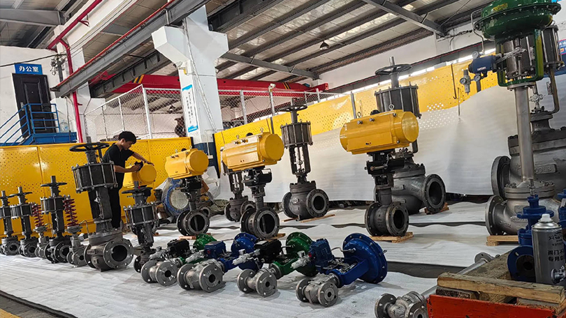
Key Components of a Control Valve Assembly
A complete control valve assembly consists of several components that work together to provide accurate, reliable flow control. Understanding each component is essential for proper selection, installation, and maintenance.
Valve Body
The valve body houses the internal trim (seat, disc/plug, cage, stem) and contains the process fluid under pressure. It provides the flow path and connection to the piping system. Body materials are selected based on pressure class, temperature, and fluid corrosivity — ranging from WCB carbon steel for general service to CF8M stainless steel, WC6/WC9 alloy steel, and Hastelloy for severe service. End connections include flanged (raised face, RTJ), threaded, butt-weld, socket-weld, and clamp-type (sanitary).
Actuator
The actuator provides the mechanical force required to position the valve’s throttling element. Actuators are classified by their power source: pneumatic (spring-diaphragm or piston), electric, electro-hydraulic, or manual (handwheel for backup). The actuator must generate sufficient thrust to overcome the unbalanced forces from process pressure, packing friction, and flow-induced forces at all valve positions. Actuator sizing is one of the most critical steps in control valve selection.
Positioner
The positioner is a precision control device mounted on the actuator that receives the control signal (4-20 mA, 3-15 PSI, or digital fieldbus) and adjusts the actuator’s position accordingly. It compares the input signal to the actual valve stem position (feedback signal) and modulates the actuator supply pressure or power until the positions match. Modern digital positioners (also called smart positioners) offer advanced features including HART or Foundation Fieldbus communication, auto-calibration, diagnostic monitoring, valve signature analysis, and predictive maintenance alerts.
I/P Transducer
The current-to-pressure (I/P) transducer converts a 4-20 mA electronic control signal into a proportional 3-15 PSI pneumatic signal for the positioner or actuator. In smart digital positioners, the I/P function is integrated within the positioner electronics. For analog systems, a stand-alone I/P transducer is used. Accuracy, air consumption, vibration resistance, and response time are key selection criteria for I/P transducers.
Accessories
Common control valve accessories include: air filter regulators (to provide clean, regulated supply air), solenoid valves (for on-off shutoff or emergency shutdown), volume boosters (to increase actuator speed), limit switches (for remote position indication), and locking devices or handwheels (for manual backup operation during instrument air failure).
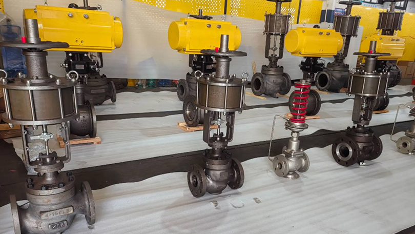
Control Valve Selection Guide: Types of Control Valves
Control valves are classified by the motion of the internal throttling element (linear vs. rotary stroke) and by the internal trim design. Each type has distinct advantages for specific applications, pressure ranges, and fluid characteristics.
1. Globe-Style Control Valve
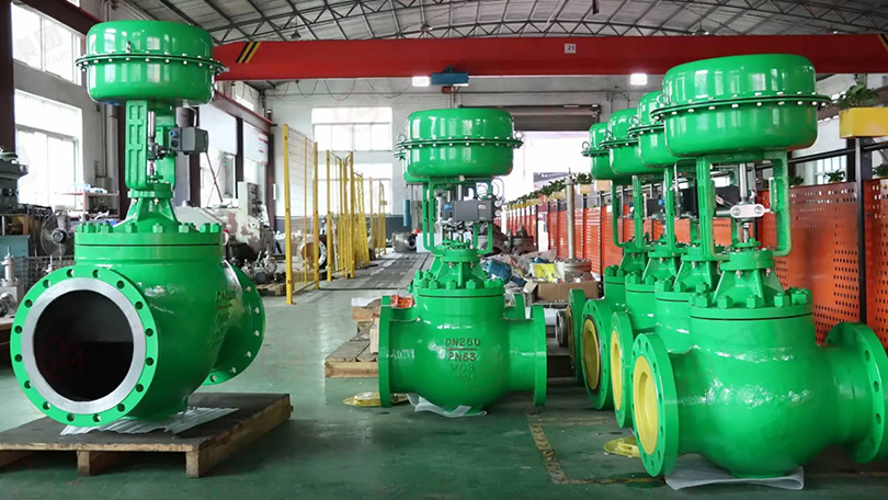
The globe-style control valve uses a linear-motion plug that moves perpendicular to the seat ring to regulate flow. Specifically, It is the most widely used control valve type in the process industry, offering excellent throttling accuracy, a wide range of Cv values, and compatibility with high-pressure and high-temperature services. The flow path through a globe control valve changes direction, creating a predictable pressure drop that enables stable control even under varying process conditions. Globe-style control valves are available in single-port (for standard throttling) and double-port (for reduced actuator force requirements in high-pressure applications) configurations. Cage-guided globe valves (described below) are the most common variant.
2. Rotary Control Valve (Ball Valve)
Rotary control ball valves use a quarter-turn (90-degree) rotating ball with a cylindrical or segmented bore to regulate flow. The ball rotates from fully open (bore aligned with flow path) to fully closed (solid face blocking flow). Segmented ball valves (also called V-notch or V-port ball valves) use a V-shaped notch in the ball that provides an equal-percentage flow characteristic ideal for control applications. Rotary control ball valves offer high flow capacity (Cv), tight shutoff, low cost relative to globe valves of the same size, and resistance to clogging in dirty or viscous services. They are widely used in pulp and paper, mining, oil and gas, and water treatment applications.
3. Rotary Control Valve (Butterfly Valve)
Butterfly control valves use a rotating disc that pivots in the center of the pipe to regulate flow. High-performance butterfly valves with eccentric disc designs (double-offset and triple-offset) provide excellent throttling characteristics, bubble-tight shutoff, and long service life. Butterfly control valves are the most economical choice for large pipe sizes (NPS 6″ and above) and are widely used in water distribution, HVAC, power plant cooling water, and low-pressure gas applications. Their compact face-to-face dimensions and lightweight construction reduce installation cost and piping support requirements.
4. Cage-Guided Control Valve
Cage-guided control valves are a specialized type of globe-style valve where the plug moves within a cylindrical cage that serves both as a flow-directing element and as a plug alignment guide. The cage contains precisely machined openings (ports) that determine the flow characteristic — linear, equal percentage, or quick opening — without changing the plug or seat. Cage guidance provides superior vibration dampening, reduced noise generation, and protection against side-loading of the stem. Cage-guided valves are the preferred choice for high-pressure drop applications, services with high fluid velocities, and applications requiring anti-cavitation or low-noise trim. The cage also facilitates easy trim replacement without removing the valve body from the pipeline.
5. Diaphragm Valve
Diaphragm valves use a flexible membrane (diaphragm) clamped between the valve body and bonnet. When the actuator pushes a compressor down onto the diaphragm, it seals against a weir in the body, throttling flow. When lifted, flow passes freely over the weir. Diaphragm valves are ideal for sanitary, pharmaceutical, food, and bioprocessing applications because the weir-body design eliminates crevices and dead spaces where bacteria could grow. The diaphragm completely isolates the bonnet and actuator from the process fluid, making these valves suitable for corrosive or sterile media. Materials include PTFE, EPDM, and silicone diaphragms with body materials of 316L stainless steel, PVC, CPVC, and polypropylene.
Control Valve Flow Characteristics
The relationship between the valve’s opening (stem travel) and the resulting flow rate (Cv) is called the flow characteristic. For example, Selecting the correct characteristic is critical for stable process control. The three standard characteristics per IEC 60534 are described below.
Linear Characteristic
In a linear characteristic valve, the flow capacity (Cv) increases proportionally with stem travel. A 50% stem position produces approximately 50% of the full-open Cv. Linear characteristics are best suited for processes where the pressure drop across the valve remains relatively constant regardless of flow rate — such as level control in tanks, flow control with constant differential pressure, and certain temperature control applications. Linear valves provide consistent gain (change in flow per change in signal) across the entire operating range.
Equal Percentage Characteristic
Equal percentage (EQ%) is the most common characteristic for throttling control. In an equal percentage valve, equal increments of stem travel produce equal percentage changes in the existing flow coefficient. For example, moving from 50% to 60% travel might increase Cv by 25% of the current value, while moving from 60% to 70% travel also increases Cv by 25% of the new value. This characteristic compensates for the decreasing pressure drop across the valve as flow increases in a typical system. Equal percentage valves provide stable control across a wide range of process conditions and are the default choice for pressure control, temperature control, and flow control in systems with varying differential pressure.
Quick Opening Characteristic
Quick opening valves provide maximum flow increase at the beginning of stem travel. A small initial stem movement (10-20% travel) produces a large change in Cv (typically 70-80% of full Cv). Quick opening characteristics are used primarily for on-off and emergency shutdown applications where rapid flow initiation is required. They are also used in relief valve and dump valve applications. Quick opening is not recommended for precise throttling control because the gain is very high at low openings and very low at high openings, making stable control difficult.
Actuator Types for Control Valves
The actuator is the power source that positions the control valve’s internal element. The choice of actuator type depends on the available utility supply, required thrust, stroking speed, fail-safe requirements, and environmental conditions.
Pneumatic Spring-Diaphragm Actuator
The spring-diaphragm actuator is the most common actuator type in the process industry. It consists of a flexible diaphragm connected to the valve stem through a spring-loaded plate. Pneumatic pressure applied to the diaphragm chamber compresses the spring and moves the stem. Loss of supply air causes the spring to return the stem to its fail-safe position (fail-open or fail-closed depending on spring orientation). Advantages include simple construction, low cost, reliable fail-safe operation, and a long service life. Limitations include limited thrust capability (typically suitable up to Class 600 for smaller valves) and susceptibility to supply pressure variations.
Pneumatic Piston Actuator
Piston actuators use a piston in a cylinder instead of a diaphragm, supplied with pneumatic pressure. They generate significantly higher thrust than spring-diaphragm actuators of the same size and can operate at higher supply pressures (up to 150 PSI or more). Piston actuators are used for high-pressure control valves (Class 900 and above), large valve sizes, and applications requiring fast stroking speeds. Fail-safe operation requires an external spring module or a hydraulic/pneumatic fail-safe system since piston actuators do not have a built-in fail-safe spring as diaphragm actuators do.
Electric Actuator
Electric actuators use an electric motor (AC or DC) coupled to a gear train and a stem nut to convert rotary motion into linear or quarter-turn motion. They are self-contained units requiring only electrical power — no instrument air is needed. Modern electric actuators offer precise position control with resolution down to 0.1%, integrated positioners with fieldbus communication (Profibus, Modbus, Foundation Fieldbus), and fail-safe options using springs or batteries. Electric actuators are preferred in remote locations without instrument air supply, in clean rooms (no exhaust air), and in applications requiring data logging and sophisticated diagnostics. Their primary disadvantage is higher initial cost compared to pneumatic actuators.
Hydraulic Actuator
Hydraulic actuators use pressurized hydraulic fluid to generate very high thrust forces in a compact package. They are used for the most demanding control valve applications — very high pressure (Class 2500+), very large valve sizes (NPS 24″ and above), and applications requiring extremely fast stroking speeds or precise positioning under high unbalanced loads. Hydraulic actuators can maintain position without continuous power consumption using lock valves. They require a hydraulic power unit (pump, reservoir, accumulator) and are typically specified for specialized applications such as turbine control, high-pressure let-down stations, and subsea production systems.
Critical Selection Criteria for Control Valves
Proper control valve selection requires a thorough analysis of process conditions, fluid properties, and performance requirements. The following criteria are essential for correct sizing and selection.
Flow Coefficient (Cv)
The flow coefficient Cv is the number of US gallons per minute of water at 60°F that will flow through the valve with a 1 PSI pressure drop. Cv is the fundamental sizing parameter for control valves and is calculated using the standard ISA-75.01 sizing equations. The required Cv depends on the maximum and normal flow rates, inlet pressure, allowable pressure drop, specific gravity, temperature, and whether the flow is laminar, turbulent, or choked. Undersizing leads to insufficient flow capacity and excessive pressure drop; oversizing causes poor control at low flow rates (the valve operates near its closed position where gain is high and control is unstable). The general rule is to select a valve such that the normal operating position is between 50% and 80% open.
Pressure Drop and Choked Flow
The pressure drop across a control valve affects both the flow rate and the potential for cavitation or flashing. As flow velocity increases through the valve restriction, the static pressure drops. If the pressure at the vena contracta (the minimum cross-section area inside the valve) falls below the fluid’s vapor pressure, vapor bubbles form (flashing). If the bubbles subsequently collapse as pressure recovers downstream, cavitation occurs. Cavitation can cause severe physical damage to valve trim, noise, and vibration. The pressure recovery factor (FL) quantifies a valve’s tendency to cavitate — lower FL values indicate higher pressure recovery and greater cavitation risk. Anti-cavitation trim designs use multiple stages of pressure reduction to keep the pressure above vapor pressure throughout the valve.
Noise Prediction and Control
Control valves are a major source of noise in industrial plants, generated by turbulent flow, mechanical vibration, and cavitation. Valve noise is predicted using the IEC 60534-8-3 standard for aerodynamic noise and IEC 60534-8-4 for hydrodynamic noise. Excessive noise indicates high fluid energy dissipation that can damage trim components and cause piping vibration. Low-noise trim designs — including multi-stage pressure reduction, tortuous-path cages, and diffuser plates — reduce noise by 10-20 dBA compared to standard trim. For applications where noise must be controlled for occupational or environmental compliance, low-noise control valves, inline silencers, and acoustic insulation are available.
Rangeability and Turndown
Rangeability is the ratio of maximum controllable Cv to minimum controllable Cv. Turndown is the ratio of maximum to minimum flow rate the valve can control within acceptable accuracy. A valve with good rangeability (50:1 or higher) can handle both high-flow and low-flow conditions without requiring a second parallel control valve. Globe-style control valves typically offer rangeability of 30:1 to 50:1, while segmented ball valves can achieve 100:1 or higher. Rangeability requirements should be matched to process flow variations: batch processes with wide flow swings need high rangeability, while continuous processes with stable flow rates need moderate rangeability.
Control Valve vs. On-Off Valve: Key Differences
Control valves and on-off (isolation) valves serve fundamentally different purposes in a piping system. Understanding when to use each type is critical for proper system design and reliable operation.
| Characteristic | Control Valve | On-Off Valve |
|---|---|---|
| Primary Function | Regulate flow at any position between open and closed | Isolation — fully open or fully closed only |
| Positioning | Modulated to any intermediate position (e.g., 45% open) | Binary — either fully open (100%) or fully closed (0%) |
| Actuator | Positioner-controlled actuator with precise stem positioning | Simple open/close actuator (spring-return or double-acting) |
| Throttling Precision | Excellent — position accuracy within 0.5-1.0% of span | None — not designed for intermediate positioning |
| Trim Design | Specially profiled plug/cage for specific flow characteristic | Standard gate, ball, or disc for maximum flow area |
| Cv vs. Pipe Size | Lower Cv for same pipe size — designed for pressure drop | Higher Cv — minimal pressure drop when fully open |
| Control Signal | Receives 4-20 mA, 3-15 PSI, or fieldbus control signal | Receives discrete on/off signal (24 VDC, 120 VAC, or pilot air) |
| Fail-Safe Position | Maintain last position, or move to fail-open/fail-closed on signal loss | Spring-return to fail-open or fail-closed on power/air loss |
| Cycle Life | Designed for frequent cycling (thousands to millions of cycles) | Designed for infrequent operation (tens to hundreds of cycles per year) |
| Cost | Higher — positioner, smart electronics, precision trim add cost | Lower — simpler actuator, no positioner, standard trim |
| Typical Service | Process control, flow regulation, pressure/temperature control | Isolation, block valve, emergency shutdown, on/off service |
A critical design rule: never use an on-off valve for throttling service. Partial opening of a gate valve or ball valve designed for on-off service causes high-velocity flow across the seat, wire drawing, seat erosion, and premature failure. Conversely, a control valve may be used for isolation if it provides tight shutoff, but it is not the most economical choice when only isolation is required.
Applications by Industry
Control valves are used across nearly every industrial sector that requires automated process control. The following describes key applications by industry.
Oil and Gas. In upstream oil and gas, control valves regulate wellhead flow, gas lift injection rates, separator level control, and pipeline pressure. In midstream, they provide custody transfer flow control at metering stations, pipeline pressure regulation, and compressor station antisurge control. In downstream refineries, control valves are used in crude distillation, catalytic cracking, hydroprocessing, sulfur recovery, and product blending. Materials range from carbon steel for sweet service to stainless steel and Incoloy for sour gas (NACE MR0175 compliant) and high-temperature services. Pressure classes from Class 150 to Class 2500.
Power Generation. Power plants use control valves extensively for boiler feedwater regulation, steam temperature control (attemperation), turbine bypass control, condensate recirculation control, and cooling water systems. Additionally, High-pressure Y-type globe control valves with anti-cavitation trim are standard for supercritical and ultra-supercritical boiler applications. Quick-opening control valves are used for turbine bypass and safety-related services.
Chemical and Petrochemical. Chemical processing requires precise control of reactants, catalysts, and product flows. Notably, Control valves handle corrosive chemicals (acids, caustics, chlorides), high-temperature processes, and hazardous fluids. Sanitary diaphragm control valves are used in specialty chemical and pharmaceutical intermediate production. Materials include 316L stainless steel, Hastelloy C276, Monel 400, titanium, and PTFE-lined bodies.
Water and Wastewater. Municipal water treatment facilities use control valves for chemical dosing (chlorine, fluoride, coagulants, polymers), filter effluent flow control, filter backwash sequencing, and distribution system pressure regulation. Large butterfly control valves (NPS 24″ to 72″) are common in raw water intake and transmission mains. Globe control valves handle chemical injection with high turndown requirements.
Pharmaceutical and Biotechnology. In pharmaceutical manufacturing, control valves must meet FDA, cGMP, and USP Class VI requirements for clean-in-place (CIP) and sterilize-in-place (SIP) operations. Weir-type diaphragm control valves with 316L SS bodies, electropolished internal surfaces, and sanitary clamp connections are standard. Applications include WFI (water for injection) distribution, bioreactor temperature control, buffer preparation, and clean steam regulation.
HVAC and Building Management. Commercial building HVAC systems use control valves for hot water, chilled water, and condenser water regulation in heating and cooling coils, radiators, heat exchangers, and cooling towers. Characterized control ball valves and globe-style control valves with 0-10 VDC or 4-20 mA control signals are typical. Applications include VAV box reheat control, chiller plant optimization, and district heating/cooling networks.
Food and Beverage. Food and beverage processing uses CIP-compatible control valves for ingredient dosing, heat exchanger temperature control, carbonation, and packaging line flow regulation. Materials include 304L and 316L stainless steel with EPDM, silicone, or PTFE seals. Diaphragm control valves are preferred for viscous fluids, particulate-containing products, and applications requiring full drainability.
Control Valve Class 300 Selection Guide
The following selection guide provides a practical reference for specifying control valves in Class 300 applications, which are among the most common pressure classes in industrial process systems. Proper selection ensures reliable control, long service life, and cost-effective operation.
Table 1: Control Valve Type Selection by Service Condition (Class 300)
| Service Condition | Recommended Valve Type | Max Cv (NPS 4″) | Max Temperature | Best For |
|---|---|---|---|---|
| General throttling, clean fluids | Globe-style (cage-guided) | 120-180 | 425°C (WCB body) | Water, steam, oil, gas |
| High-pressure drop, cavitating services | Globe-style (anti-cavitation cage) | 80-140 | 425°C (WCB body) | Boiler feedwater, condensate |
| High flow, low ΔP, clean fluids | Rotary control ball (segmented V-ball) | 250-400 | 350°C (316 SS body) | Pulp stock, slurries, gas |
| Large pipe size, low ΔP | High-performance butterfly (double-offset) | 400-2500+ | 350°C (316 SS body) | Water, air, HVAC, cooling water |
| Sanitary, sterile, food/pharma | Weir-type diaphragm valve | 40-150 | 150°C (PTFE diaphragm) | WFI, CIP, bioprocessing |
| Severe service, high noise | Globe-style (low-noise cage trim) | 60-120 | 425°C (WCB/WC6 body) | High-pressure gas, steam vent |
| Corrosive fluids | Globe-style (PTFE-lined or alloy body) | 50-100 | 200°C (PTFE-lined) | Acids, caustics, chlorides |
| Viscous or dirty fluids | Rotary control ball (full-bore) | 300-500 | 300°C (316 SS body) | Slurries, heavy oils, polymers |
Table 2: Actuator Selection Guide for Class 300 Control Valves
| Valve Size | Valve Type | Breakaway Torque/Thrust | Recommended Actuator | Supply Pressure | Fail-Safe |
|---|---|---|---|---|---|
| NPS 1″ – 2″ | Globe-style | 500-1500 lbf | Spring-diaphragm (size 35-45) | 20-60 PSI | Integral spring |
| NPS 3″ – 4″ | Globe-style | 1500-4000 lbf | Spring-diaphragm (size 50-70) | 20-80 PSI | Integral spring |
| NPS 6″ – 8″ | Globe-style | 4000-10000 lbf | Piston actuator | 40-120 PSI | External spring module |
| NPS 10″ – 16″ | Butterfly | 200-800 ft-lb | Spring-diaphragm rotary (sizes 50-70) | 20-80 PSI | Integral spring |
| NPS 18″ – 24″ | Butterfly | 800-3000 ft-lb | Piston rotary or electric (multi-turn) | 60-120 PSI | Spring-return or battery |
| NPS 1″ – 4″ | Rotary ball | 50-300 ft-lb | Spring-diaphragm rotary (sizes 30-50) | 20-60 PSI | Integral spring |
| NPS 6″ – 12″ | Rotary ball | 300-1500 ft-lb | Piston rotary or electric (multi-turn) | 40-120 PSI | External spring or battery |
| NPS 1″ – 4″ | Diaphragm (weir) | 200-1000 lbf | Spring-diaphragm (size 30-45) | 20-60 PSI | Integral spring |
When selecting a control valve for Class 300 service, consider the following: (1) Cv requirements at both normal and maximum flow conditions; (2) Inlet pressure and allowable pressure drop based on system hydraulics; (3) Fluid properties including specific gravity, viscosity, vapor pressure, and solids content; (4) Process temperature range and ambient temperature conditions for the actuator; (5) Required flow characteristic (linear, equal percentage, or quick opening); (6) Rangeability requirements — batch processes with wide flow swings need high rangeability; (7) Fail-safe position requirements (fail-open, fail-closed, or lock-in-last-position); and (8) Communication protocol compatibility with the existing DCS or PLC system.
Conclusion
Control valves are the essential final control elements that make automated process control possible across virtually every industrial sector. From simple pressure regulation in a water treatment plant to high-pressure let-down in a petrochemical refinery, control valves translate electronic control signals into precise physical adjustments of flow area, enabling stable, safe, and efficient process operation. The selection of the correct control valve type — whether globe-style for precise throttling, rotary ball for high capacity, high-performance butterfly for large diameters, cage-guided for severe services, or diaphragm for sanitary applications — depends on a careful evaluation of process conditions, fluid properties, performance requirements, and lifecycle cost.
Key considerations in any control valve selection include the required flow coefficient (Cv), pressure drop and cavitation risk, noise predictions, rangeability, material compatibility with the process fluid, actuator type and fail-safe configuration, and communication protocol compatibility. The Class 300 selection guide provided in this article serves as a practical reference for the most common industrial control valve applications, covering valve type selection by service condition and actuator sizing by valve size and type.
As industrial automation advances with digitalization, Industry 4.0, and the Industrial Internet of Things (IIoT), control valves are evolving from simple mechanical regulators into intelligent field devices with embedded diagnostics, predictive maintenance capabilities, and wireless communication. Smart positioners with HART, Foundation Fieldbus, and PROFIBUS PA protocols enable condition monitoring, valve signature analysis, and real-time performance tracking that reduce unplanned downtime and optimize maintenance intervals. Selecting a control valve today means choosing not just a mechanical device, but a smart instrument that will integrate with the plant’s digital infrastructure for years to come.
Vornet Valve manufactures a comprehensive range of control valves in carbon steel (WCB, WCC, LCB), stainless steel (CF8, CF8M, CF3M), and alloy steel (WC6, WC9), with sizes from NPS 1/2″ to 24″ and pressure classes from Class 150 to Class 2500. Vornet control valves are designed with standard and custom trim options including anti-cavitation, low-noise, and erosion-resistant configurations. All Vornet control valves are designed, manufactured, and tested in accordance with IEC 60534, ASME B16.34, and API 598 standards, ensuring reliable performance in the most demanding process control applications.
Need a Control Valve for Your Process System?
Vornet Valve manufactures control valves in carbon steel, stainless steel, and alloy steel — NPS 1/2″ to 24″, Class 150 to 2500. Pneumatic, electric, and hydraulic actuation available.
• Control Valve Selection Guide: Types, Actuation, Sizing
• Globe Valve Complete Guide
• Pipeline Strainer Guide