
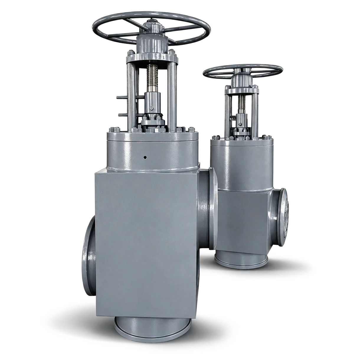
High-Pressure Feedwater Heater Isolation Valves
Product Description
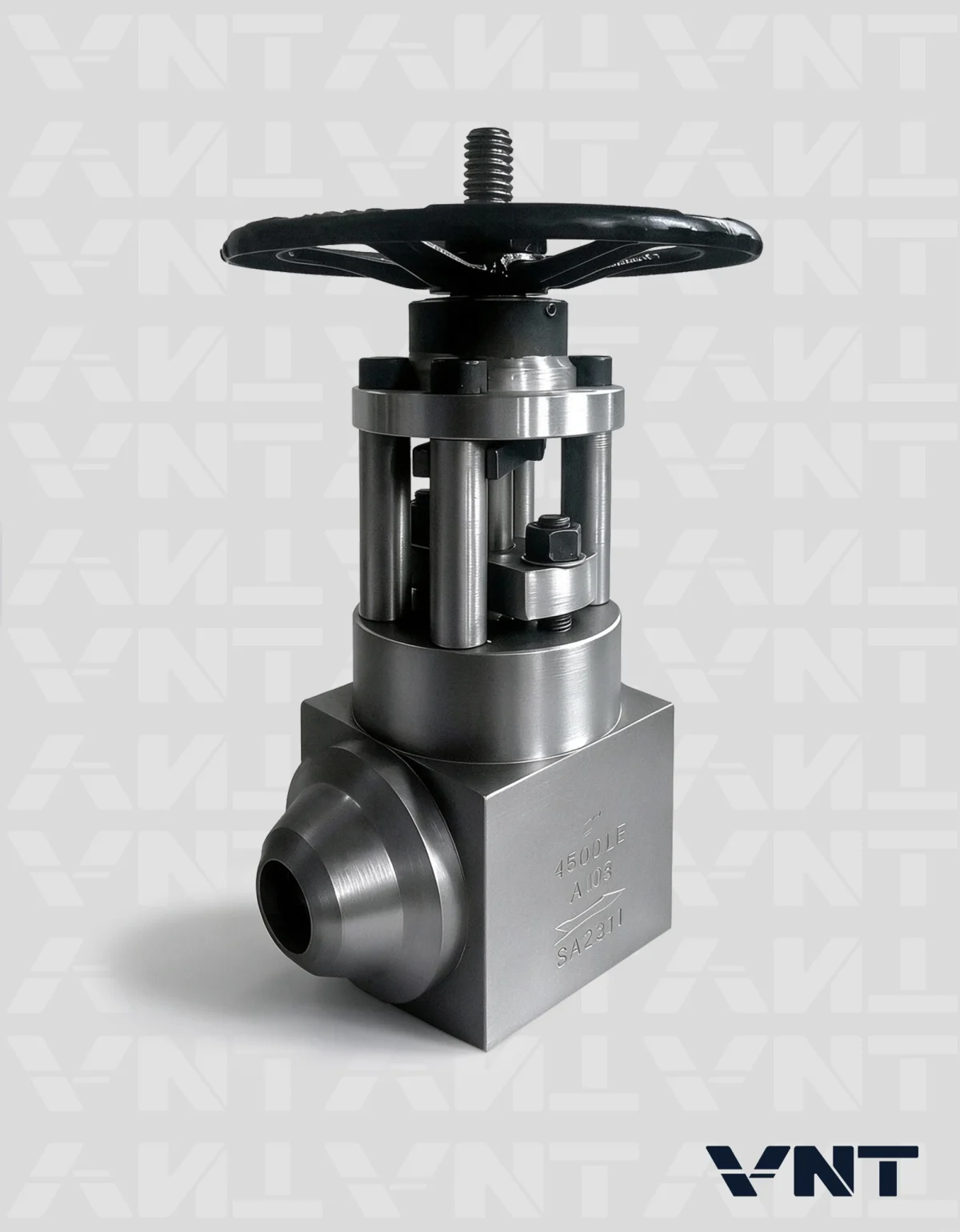
High-pressure feedwater heater isolation valves are installed at the inlet and outlet of a feedwater heater in a thermal power plant. The paired valves isolate the heater and direct feedwater through the bypass when the plant protection system detects a high-water-level condition.
The feedwater heater isolation and bypass system maintains the feedwater route to the boiler while the affected heater is taken out of service. Valve configuration, closing duty and control logic are selected for the project piping arrangement.
How the Feedwater Heater Isolation System Works
Normal operation: Feedwater passes through the heater inlet and outlet valves, with the bypass closed.
Heater protection: On a high-water-level trip signal, the feedwater heater isolation valves close the heater flow paths and open the bypass to maintain feedwater supply to the boiler. Closing sequence and timing follow the approved plant control logic.
Return to service: After the fault is resolved, follow the approved procedure for pressure equalization, reset and interlocks.
Key Features
- Coordinated inlet and outlet isolation for high-pressure feedwater heaters.
- Bypass flow path to maintain boiler feedwater supply when the heater is isolated.
- Changeover duty coordinated with the heater high-water-level protection signal.
- Valve materials, connections and actuation selected for the specified operating conditions.
- Closing time, failure action and test acceptance confirmed in the approved project documents.
General Information
| Size Range | NPS 6–28 (DN150–DN700) |
|---|---|
| Pressure Rating | Class 1500–2500 / PN200–PN500 |
| Body Material | Carbon Steel, Alloy Steel, Stainless Steel, WB36 |
| Temperature Range | Material-dependent; confirm against design temperature and the applicable pressure–temperature rating. |
| Operation | Project-specific actuation; confirm the control and failure-action requirements. |
| Design Standard | ASME B16.34 |
| Face to Face Dimension | Manufacturer’s standard or approved project drawing |
| Ends Connections | ASME B16.25 |
| Test & Inspection | API 598 |
Class and PN are separate rating systems, not direct equivalents. Confirm the specified standard and pressure–temperature rating for the selected material.
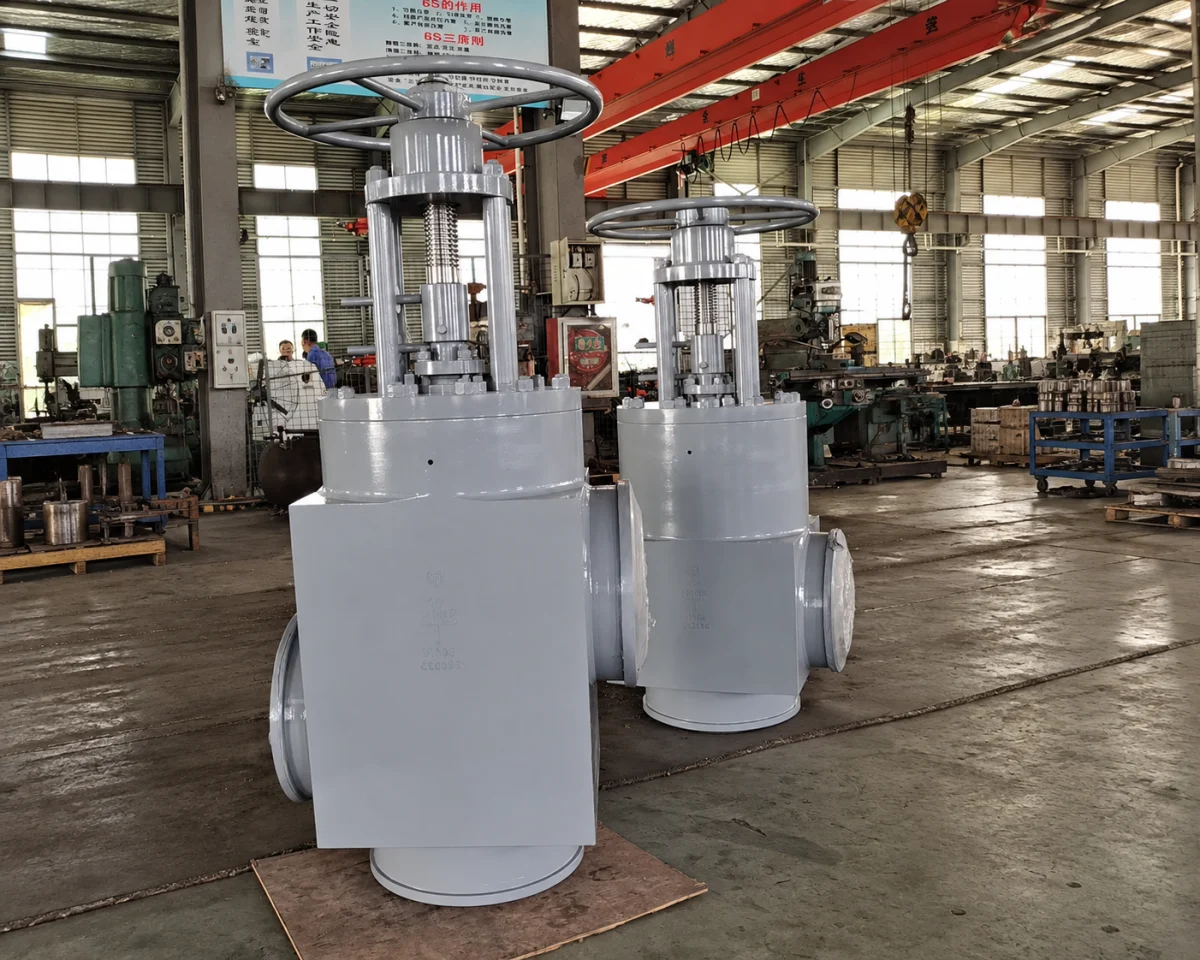
Heater Isolation Valve Selection Information
Heater and piping
P&ID or piping schematic; heater arrangement; inlet, outlet and bypass line sizes; flow direction and installation orientation.
Feedwater conditions
Normal and design pressure and temperature; minimum, normal and maximum feedwater flow; relevant differential pressures.
Valve specification
NPS or DN, specified Class or PN standard, body and trim materials, BW preparation, pipe wall thickness and required dimensions.
Protection and controls
Trip signal, required closing time and sequence, actuator supply, loss-of-supply action, interlocks and position indication.
Replacement requirements
Existing valve drawing, available installation space, connection dimensions and operating history, where applicable.
Inspection and delivery
Quantity, destination and delivery date; leakage acceptance, material certificates, inspection plan and functional-test requirements.
Fill in your heater valve enquiry
Heater Isolation Valve Enquiry
Enter the operating data you have. Technical fields can be left blank if unknown. Fields marked * are required.
Power Plant
Valve Projects
Explore Vornet valve projects for power plants, including gate valves for isolation and automatic recirculation valves for pump protection.
View All Case Studies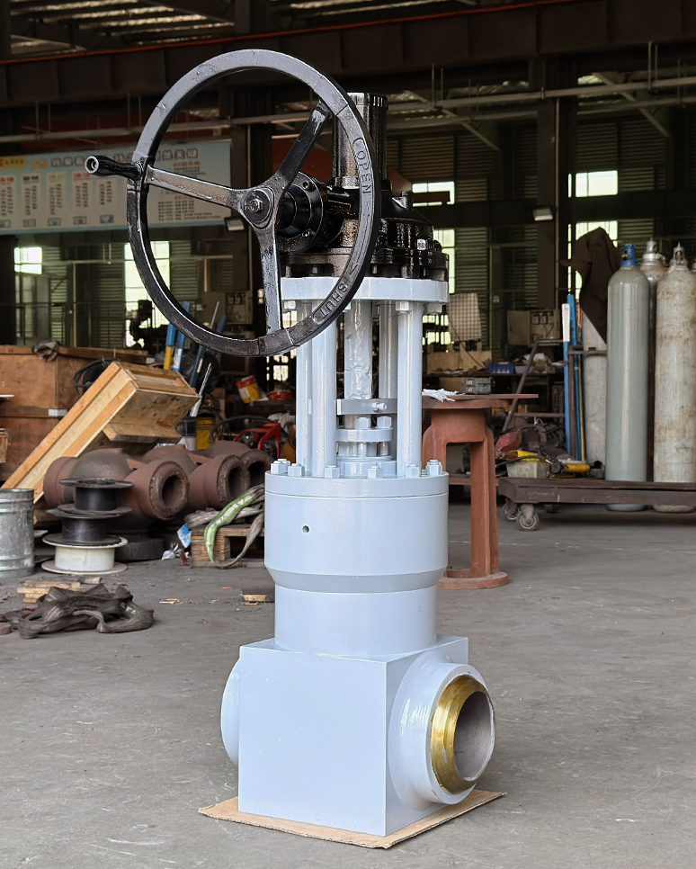
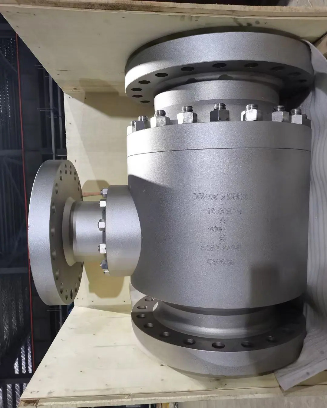
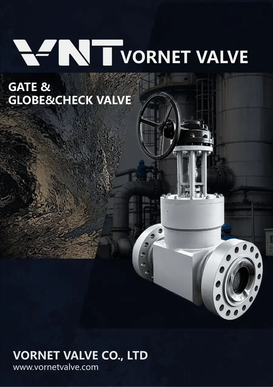
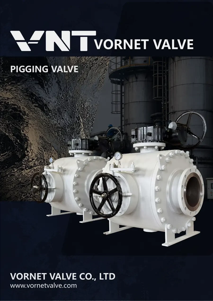
Related Industrial Valves
Related
Documents
Download Vornet valve catalogues. For this heater isolation system, request a project-specific datasheet, general arrangement drawing and control diagram.
Explore All Downloads ↗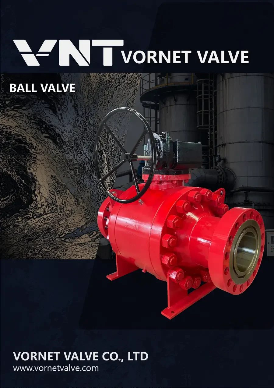
What is a feedwater heater isolation valve system?
It is an inlet, outlet and bypass valve arrangement used to isolate a high-pressure feedwater heater while maintaining the required feedwater route to the boiler.
When does the feedwater heater bypass open?
During a heater protection event, such as a high-water-level signal following a tube leak, the specified valve sequence isolates the heater and establishes the bypass path. The final sequence follows the approved plant control logic.
Is a heater isolation valve the same as a feedwater control valve?
No. Heater isolation and bypass valves select the feedwater route around a heater. A feedwater control valve regulates flow or boiler water level. The valves serve different duties and are selected separately.
What sizes, pressure ratings and materials are listed?
The published series range is NPS 6–28 (DN150–DN700), Class 1500–2500 / PN200–PN500, with carbon steel, alloy steel, stainless steel and WB36 options. Class and PN are separate rating systems, not direct equivalents. Confirm each size, material and pressure–temperature combination in the project datasheet.
How are closing time and failure action specified?
Specify the protection signal, required closing sequence and time, actuator supply and action on loss of power or control supply. Confirm these requirements against the selected valve design, control diagram and agreed functional test.
What information is required for selection and quotation?
Provide the P&ID, inlet, outlet and bypass sizes, feedwater pressure, temperature and flow, materials, BW preparation, actuation and control requirements. Include quantity, delivery date, inspection and documentation requirements.