\n\n\n\n 3-Way Ball Valve Applications: Mixing, Diverting, and Flow Selection | Vornet Valve 838209&ev=PageView&noscript=1" />
jessamynlee@vornetvalve.com / jessamyn@vornetvalve.com 📞 +86-17888190118 🌐 EN  |  🇷🇺 RU

3-Way Ball Valve Applications: Mixing, Diverting, and Flow Selection for Industrial Piping Systems

📌 Quick Summary:

3-way ball valves route flow between three ports for mixing, diverting, or flow selection in industrial piping systems. The choice between L-port and T-port configurations determines whether the valve isolates the unused port or allows simultaneous multi-port flow. This guide covers port configurations, selection criteria, application-specific recommendations, and comparison tables for engineers and procurement specialists.

📋 Key Takeaways

  • 3-way ball valves serve three core functions: mixing (T-port), diverting (L-port), and flow selection (L-port) — choosing the wrong port configuration causes operational failure.
  • L-port ball valves provide positive isolation of the unused port, making them essential for applications where cross-contamination between branches cannot be tolerated.
  • T-port ball valves can connect all three ports simultaneously, enabling mixing and blending but offering only partial isolation of the unused branch in diverting service.
  • Class 150 3-way ball valves are the most common pressure class for general industrial applications, covering water, air, chemicals, and HVAC services up to 285 psi.
  • A single 3-way ball valve can replace multiple 2-way valves in many routing applications, reducing component count, installation cost, and potential leak paths.
3-Way Ball Valve Applications

A 3-way ball valve is one of the most versatile components in industrial fluid handling. Unlike a standard two-way valve that simply opens or closes a single flow path, a 3-way ball valve can route flow between three ports, allowing an engineer to mix two incoming streams into one outlet, divert one incoming stream into two separate outlets, or select between two fluid sources for a common discharge line. These capabilities make 3-way ball valve applications essential across virtually every processing industry — from chemical plants and refineries to water treatment facilities, pharmaceutical manufacturing, and HVAC systems.

Despite the apparent simplicity of adding a third port, the internal geometry of the ball itself determines the valve’s behavior. The two main configurations — L-port (90-degree port) and T-port (180-degree port) — produce fundamentally different flow patterns. Choosing the wrong configuration for your application can lead to cross-contamination, dead-leg stagnation, pressure loss, or operational inefficiency. This guide provides a complete technical reference for 3-way ball valve applications, covering port configurations, flow patterns, selection criteria, comparison tables, and application-specific recommendations.

What Is a 3-Way Ball Valve?

A 3-way ball valve has three ports (inlet/outlet connections) and a spherical ball with internal passages machined in an L-shaped or T-shaped pattern. The ball rotates 90 degrees (quarter-turn) to align the internal passage with different port combinations. The valve body is typically cast or forged in materials such as WCB (carbon steel), CF8M (316 stainless steel), CF3M (316L stainless steel), or alloy steel grades, depending on the service conditions.

The three ports are conventionally labelled A, B, and AB. Port AB is the common port, always connected to the ball passage. Ports A and B are the branch ports that connect to the common port depending on the ball position. In an L-port valve, the ball has a single 90-degree passage that connects two adjacent ports at a time. In a T-port valve, the ball has a 180-degree passage (or a full T-shaped passage) that can connect all three ports simultaneously or in various combinations.

The fundamental distinction between the two configurations is:

  • L-port ball valve: The ball passage forms a 90-degree turn. Flow enters one port and exits through an adjacent port. Used for diverting flow between two outlets or selecting between two inlets. The third port is always isolated.
  • T-port ball valve: The ball passage forms a straight-through channel with a branch. Flow can pass straight from port A to port B while port AB is open, or all three ports can be connected simultaneously. Used for mixing two streams into one or splitting one stream into two.

The Three Core 3-Way Ball Valve Applications

All 3-way ball valve applications fall into three functional categories: mixing, diverting, and flow selection. Understanding which configuration to use for each application is critical to proper system design.

1. Mixing Applications

In a mixing application, two separate fluid streams enter through ports A and B and combine into a single outlet stream through the common port AB. This is accomplished with a T-port ball valve positioned so that the internal passage connects all three ports simultaneously. The mixing ratio depends on the upstream flow rates and pressures — the valve itself does not proportion the flow; it simply provides a common chamber where the two streams can combine before exiting.

Common mixing applications include:

  • Chemical blending: Combining two chemical components in a reactor feed line where the fluids must be mixed before entering the vessel
  • Temperature control: Mixing hot and cold water or heat transfer fluids to achieve a precise set-point temperature in heating or cooling loops
  • pH adjustment: Blending an acid or base stream with a process stream to maintain a target pH range
  • Additive injection: Introducing a concentrated additive or inhibitor into a main process flow at a controlled ratio
  • Waste neutralization: Combining acidic and alkaline waste streams to achieve a neutral effluent before discharge or further treatment

For mixing applications, the T-port valve must be selected with care. The mixing chamber inside the ball creates turbulence that promotes blending, but it also introduces pressure drop. A full-port T-port design minimizes restriction, while a reduced-port design increases velocity and mixing intensity at the cost of higher pressure loss.

2. Diverting Applications

In a diverting application, a single inlet stream enters through the common port AB and is directed to either port A or port B. This is the most common 3-way ball valve application in industrial piping, and it can be accomplished with either an L-port or a T-port valve depending on whether isolation of the unused branch is required.

An L-port ball valve is the preferred choice for diverting when isolation is mandatory. In the L-port design, the ball’s 90-degree passage connects AB to A in one position and AB to B in the other position. The unused port is completely isolated by the solid wall of the ball. This prevents any leakage between the two branch lines — critical in applications where cross-contamination cannot be tolerated.

A T-port ball valve can also be used for diverting, but with an important caveat: when the ball connects AB to A, the passage to B is not fully isolated. Depending on the T-port geometry, there may be a partial open path to the unused port, allowing pressure bleed or minor leakage into the dead leg. For true diverting with positive shut-off on the unused branch, an L-port is the correct choice.

Common diverting applications include:

  • Filter changeover: Directing flow to one filter vessel while the other is taken offline for cleaning or media replacement — the isolated port prevents process fluid from entering the offline vessel
  • Heat exchanger bypass: Routing flow through a heat exchanger for temperature control or bypassing it entirely during maintenance or warm-up
  • Tank filling / emptying: Directing product from a common supply line into one tank while another tank is being emptied, filled, or sampled
  • Vessel isolation: Selecting between two process vessels (reactors, separators, storage tanks) for feeding or receiving product from a common line
  • Sampling systems: Diverting flow from a main line to a sample station while keeping the main process uninterrupted

3. Flow Selection Applications

Flow selection — sometimes called source selection or inlet selection — is the reverse of diverting. Instead of directing one inlet to two outlets, flow selection allows an operator to choose between two inlet sources (ports A and B) for a single outlet (port AB). This is commonly used in backup or standby systems where a secondary fluid source must be available without cross-contamination between the two sources.

As with diverting, an L-port ball valve is preferred for flow selection when the two sources must remain completely isolated from each other. The L-port design ensures that only one source is connected to the outlet at any time, with the other source fully blocked by the solid ball surface.

Common flow selection applications include:

  • Dual pump systems: Selecting between a primary pump and a standby pump for feeding a process line — the primary source is used during normal operation, and the secondary source is brought online without cross-flow between pumps
  • Alternate supply sources: Switching between a main water supply and a backup storage tank or between two chemical feed drums
  • Gas supply manifolds: Selecting between a primary gas supply (pipeline, cylinder bank) and a reserve supply for continuous gas delivery to a process or instrument air system
  • Steam selection: Choosing between high-pressure and low-pressure steam sources for a heating application, with positive isolation of the unused source
  • Backup cooling circuits: Selecting between normal cooling water and emergency cooling water for critical heat exchangers in power plants or chemical reactors

L-Port vs. T-Port: Comparison Table

3-Way Ball Valve L-Port and T-Port Flow Patterns

The following table provides a direct comparison between L-port and T-port 3-way ball valves across all key performance parameters:

PARAMETERL-PORT BALL VALVET-PORT BALL VALVE
Ball Passage Shape90-degree (L-shaped) single passage180-degree straight passage with branch (T-shaped)
Primary FunctionDiverting, flow selection (one inlet to two outlets or two inlets to one outlet)Mixing (two inlets to one outlet) or full flow-through
Simultaneous Port ConnectionOnly two ports connected at any timeCan connect all three ports simultaneously
Unused Port IsolationComplete — solid ball wall blocks the unused portPartial — may allow pressure communication to the unused branch
Cross-Contamination RiskNone (when properly seated)Possible if used for diverting without dead-leg precautions
Flow PathOne 90-degree turn through the ballStraight through or 90-degree branch turn
Pressure DropModerate (due to 90-degree flow redirection)Low in straight-through mode; moderate in mixing mode
Cv Flow CoefficientTypically 50–70% of equivalent full-port two-way valveTypically 70–90% of equivalent full-port two-way valve in straight-through mode
Typical Port ConfigurationAB-A or AB-B (one common, two branches)A-AB-B (all ports in line)
Actuator CompatibilityStandard 90-degree quarter-turn (can be automated)Standard 90-degree quarter-turn (may require 180-degree for some multi-position)
Cost Premium vs. 2-WayModerate (20–40% more than equivalent two-way)Moderate (25–45% more than equivalent two-way)
Best ApplicationDiverting with isolation, source selectionMixing, blending, full flow-through

3-Way Ball Valve Applications by Industry

3-way ball valve applications span a wide range of industries, each with specific requirements for materials, pressure class, actuation, and certification.

Oil and Gas

3-Way Ball Valve Oil and Gas Applications

In upstream oil and gas production, 3-way ball valves are used in test manifolds to select which well’s production is routed through a test separator. In midstream pipelines, they serve as pig launcher/receiver isolation valves and in filter changeover stations. Downstream refineries use L-port 3-way ball valves for catalyst regeneration switching, product routing to different storage tanks, and cooling water selection for process heat exchangers. Materials are typically A216 WCB or A352 LCC for low-temperature service, with trim upgraded to 316 stainless steel with hard-facing for abrasive or corrosive fluids.

Chemical and Petrochemical

Chemical plants rely on 3-way ball valves for acid/caustic blending, reactor feed selection, solvent recovery routing, and waste neutralization systems. The ability to completely isolate one branch makes L-port valves ideal for toxic or reactive chemical service where cross-contamination could cause a runaway reaction. Materials range from 316L stainless steel (CF3M) for corrosive services to Alloy 20, Hastelloy C-276, or titanium for highly aggressive chemicals. PTFE or reinforced PTFE seats are standard for chemical service, with PEEK seats for higher-temperature applications.

Water and Wastewater Treatment

Municipal and industrial water treatment plants use 3-way ball valves for filter backwash sequencing, chemical dosing selection (coagulant, flocculant, polymer), disinfection chemical routing, and sludge diversion. Large-diameter 3-way ball valves (NPS 12 and above) are common in raw water intake selection and filter effluent control. Epoxy-coated ductile iron bodies with EPDM seats are typical for water service, while PVC or PP ball valves are used for chemical metering lines.

Pharmaceutical and Biotechnology

In pharmaceutical manufacturing, 3-way ball valves are used for CIP (clean-in-place) and SIP (sterilize-in-place) solution routing, WFI (water for injection) distribution selection, and buffer/media preparation blending. These applications demand full-port, cavity-filled ball valves with Ra ≤ 0.5 μm surface finish, 316L stainless steel construction, and full material traceability. Sanitary clamp connections (tri-clamp) are standard, and the valves must meet ASME BPE surface finish and drainability requirements.

Power Generation

Power plants use 3-way ball valves for cooling water selection between main and auxiliary cooling towers, turbine lube oil system filter changeover, hydrogen cooling gas supply selection for generators, and feedwater heater bypass. High-pressure Class 600 to Class 2500 configurations are common for steam and feedwater applications, with forged alloy steel bodies (A182 F22, F91) and Stellite hard-faced seats for erosion resistance at high temperatures and pressures.

HVAC and Building Services

In large commercial and industrial HVAC systems, 3-way ball valves (typically T-port) are used for hot water and chilled water mixing to achieve precise supply temperature control. They are also used for boiler isolation and changeover, condenser water routing between cooling towers, and zone temperature control in variable flow hydronic systems. Bronze or cast iron bodies with NPT threaded ends are common in smaller sizes (NPS 1/2 to 2), while flanged carbon steel or ductile iron valves are used in larger sizes.

How to Select the Right 3-Way Ball Valve for Your Application

3-Way Ball Valve Selection Guide

Selecting the correct 3-way ball valve involves evaluating several key parameters beyond just the port configuration. The following selection criteria apply to all 3-way ball valve applications:

Port Configuration

Determine whether your application requires mixing (T-port), diverting with isolation (L-port), or diverting without strict isolation (T-port or L-port). This is the single most important selection decision. An L-port valve used in a mixing application will not function correctly because only two ports can be connected at a time. A T-port valve used in an application requiring complete isolation of the unused branch may allow cross-flow or pressure bleed.

Pressure Class and Temperature Rating

Select the pressure class based on the maximum operating pressure at the maximum operating temperature per ASME B16.34. Common classes for 3-way ball valves include Class 150 (low-pressure water, HVAC, general chemical), Class 300 (medium-pressure process, refinery utilities), Class 600 (high-pressure oil and gas, steam), and Class 900/1500 (severe service, high-pressure gas). Always verify that the seat material is rated for the maximum service temperature — PTFE seats degrade above 200°C (392°F), while PEEK seats can withstand up to 260°C (500°F) and metal seats up to 540°C (1000°F).

End Connections

Select end connections compatible with your piping system: flanged (ASME B16.5 for Class 150–600, ASME B16.47 for larger sizes), threaded (NPT or BSP), socket weld, butt weld, or sanitary clamp (tri-clamp for pharmaceutical and food applications). Flanged connections are standard in industrial process applications. Threaded ends are common in smaller sizes for instrumentation, HVAC, and general utility service.

Body Material

Select the body material based on fluid corrosivity, temperature, and pressure:

  • WCB (Carbon Steel): General-purpose, non-corrosive fluids, oil and gas, water, steam up to 425°C
  • CF8M (316 SS): Corrosive fluids, chemical service, pharmaceutical, food processing
  • CF3M (316L SS): Same as CF8M but with low carbon for weldability and improved corrosion resistance in welded assemblies
  • Bronze / Brass: Low-pressure water, HVAC, plumbing applications
  • Alloy 20 / Hastelloy: Severe chemical service with strong acids (sulfuric, hydrochloric)
  • PVC / CPVC / PP: Low-pressure corrosive chemical service, water treatment chemical metering

Seat and Seal Material

The seat material determines the temperature range, leakage rate, and torque characteristics:

  • PTFE (Teflon): Excellent chemical resistance, low friction, temperature range -29°C to 200°C. Standard for most general-purpose applications.
  • Reinforced PTFE (R-PTFE / TFM): Better mechanical strength and wear resistance than virgin PTFE. Suitable for higher-pressure differentials.
  • PEEK: High temperature resistance (up to 260°C), excellent mechanical strength, good chemical resistance. Used in steam and high-temperature process applications.
  • Metal Seats (SS+ Stellite Hard-Facing): Maximum temperature resistance (up to 540°C), fire-safe, erosion-resistant. Used in severe service, high-temperature, and abrasive applications.
  • Nylon / TPE: Lower-cost alternatives for water and HVAC service with moderate temperature requirements.

Actuation Requirements

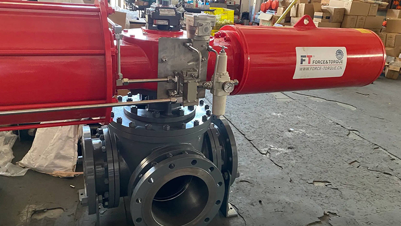
Determine whether the valve will be manually operated (lever or gearbox) or automated (pneumatic, electric, or hydraulic actuator). For automated 3-way ball valves, actuator sizing must account for the differential pressure and the additional friction from the third port’s sealing surface. Spring-return actuators are common for fail-safe diverting applications. Position feedback (limit switches, proximity sensors) is typically required for remote monitoring of the selected position.

3-Way Ball Valve vs. Multiple 2-Way Valves: Comparison Table

One common design decision is whether to use a single 3-way ball valve or a combination of two or three 2-way valves to achieve the same flow routing. The following table compares both approaches across multiple criteria:

CRITERIONSINGLE 3-WAY BALL VALVEMULTIPLE 2-WAY BALL VALVES
Component Count1 valve2–3 valves plus pipe tees and fittings
Installation FootprintCompact — single valve body in the pipe runLarge — multiple valves, tees, and connecting pipe spools
Total WeightLower — one valve body, one actuator (if automated)Higher — multiple valve bodies and fittings add structural load
Installation CostLower — fewer pipe joints, less welding or threading, less support steelHigher — more components, more installation labor, more potential leak points
Potential Leak Paths2 stem seals + 2 end seals4–6 stem seals + 4–6 end seals + threaded joints
Operational ComplexitySingle quarter-turn operation — one actuator or lever position determines routingRequires sequential operation of multiple valves — interlocking or PLC logic needed to prevent incorrect combinations
Sequencing RiskNone — valve position directly controls routing; no possibility of wrong sequenceHigh — operator could open the wrong valve combination, causing cross-flow or dead-heading a pump
Maintenance AccessSingle valve to service, but requires line shutdown for the branch being servicedIndividual valves can be isolated and serviced without shutting down the entire system (if isolation valves are provided)
Flow Capacity (Cv)Lower — the compact ball passage in a 3-way design restricts flow compared to a full-port 2-way valveHigher — each branch has a dedicated full-port valve with minimal flow restriction
Cost (Valve Only)Higher than a single 2-way valve, but lower than the total for multiple 2-way valves plus fittingsHigher total cost when summing valve bodies, tees, nipples, flanges, and gaskets
Best ForSpace-constrained installations, automated systems, applications requiring single-action routing changeoverSystems where individual branch isolation is needed, large-diameter lines, applications where ultimate flow capacity is critical

Class 150 3-Way Ball Valve Selection Guide

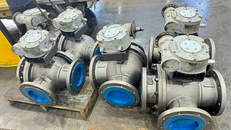
The following selection guide covers standard Class 150 3-way ball valves — the most common pressure class for general industrial 3-way ball valve applications. Class 150 is suitable for water, air, general chemical, HVAC, and low-pressure process services up to 285 psi (19.6 bar) at ambient temperature, derated at higher temperatures per ASME B16.34.

Size Range and Flow Capacity

Class 150 3-way ball valves are typically available in sizes from NPS 1/2 to NPS 12. Full-port (full bore) designs maintain the full pipe internal diameter through the valve, while reduced-port (standard port) designs have a smaller bore that reduces cost and weight at the expense of some flow capacity. For 3-way applications where pressure drop is a concern (e.g., mixing applications requiring minimum back pressure), full-port valves are recommended. For diverting or selection applications where the flow path includes a 90-degree turn through the ball regardless of port configuration, reduced-port valves are usually acceptable.

Material Selection by Fluid Service

  • Water, air, inert gases: WCB carbon steel body, 304 SS ball and stem, PTFE seats. Suitable for general utility service, instrument air, cooling water.
  • Steam (low pressure): WCB carbon steel body, 316 SS ball and stem, reinforced PTFE or PEEK seats. Note that Class 150 has limited steam pressure — maximum 150 psi at saturated steam temperature.
  • General chemicals (non-corrosive): WCB or CF8M (304 SS) body, 304 or 316 SS ball and stem, PTFE seats. For mild acids, bases, and organic solvents.
  • Corrosive chemicals: CF8M (316 SS) or CF3M (316L SS) body, 316 SS ball and stem with Alloy 20 or Hastelloy trim for severe corrosives, PTFE or PEEK seats. For sulfuric acid, hydrochloric acid, caustic soda, and aggressive solvents.
  • Hydrocarbons (refined products): WCB body with NACE MR0175/ISO 15156 compliant trim (316 SS ball, Inconel X-750 spring-energized seats), PTFE or PEEK seats. For sour service in refineries and gas plants.
  • High-purity water / WFI: 316L SS (CF3M) body with electropolished internal surfaces, full-port design, PTFE or modified PTFE seats. For pharmaceutical and semiconductor manufacturing.

Actuator Selection Guide

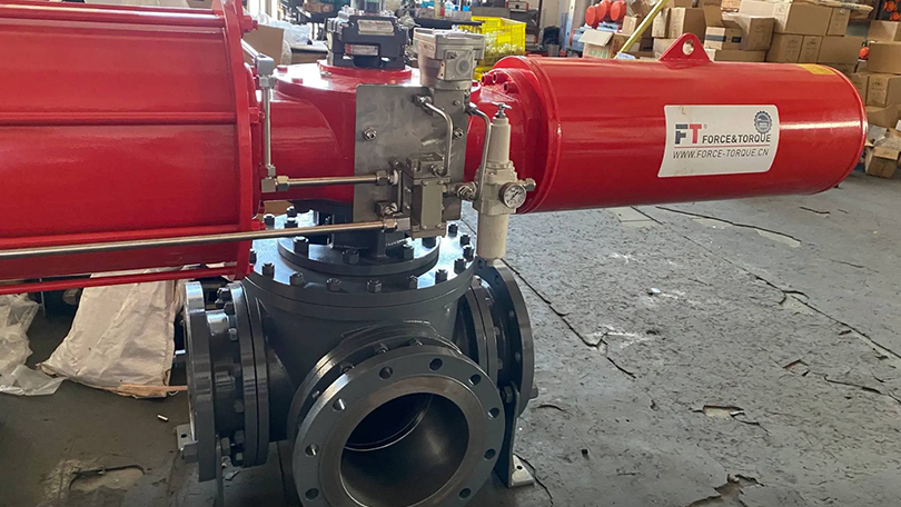
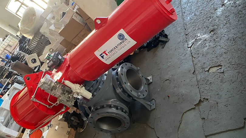
For automated Class 150 3-way ball valves, the actuator torque requirement is approximately 1.5 to 2 times that of an equivalent two-way valve due to the additional sealing surface and the unbalanced pressure forces on the ball. Pneumatic rack-and-pinion actuators are the most common choice for automated 3-way ball valves in Class 150 service, offering reliable quarter-turn operation, compact size, and low cost. For fail-safe applications (e.g., emergency diverting to a relief system), spring-return pneumatic actuators with either fail-open or fail-close action are specified. Electric actuators are preferred where compressed air is not available or where precise positioning is required.

Selection Checklist for Class 150 3-Way Ball Valves

  1. Confirm operating pressure and temperature — verify that the Class 150 rating curve in ASME B16.34 covers your conditions with margin
  2. Identify the flow pattern: mixing (T-port) or diverting/selection (L-port)
  3. Size the valve: select NPS based on pipe size and required flow rate (Cv)
  4. Select body and trim materials compatible with the fluid chemistry and temperature
  5. Choose seat material: PTFE for standard service, PEEK for high temperature, metal for severe service
  6. Specify end connections: flanged (ASME B16.5 Class 150 RF), threaded (NPT), or socket weld
  7. Determine actuation: manual lever, gearbox, pneumatic actuator, or electric actuator
  8. Verify certifications: ISO 9001, PED (CE), CRN (Canada), NACE MR0175 (if required)
  9. Confirm fire-safe design per API 607 or ISO 10497 if the service involves flammable fluids
  10. Specify test requirements: shell test, seat test (both seats), and cavity pressure relief test per API 6D or MSS SP-72

Installation and Maintenance Best Practices for 3-Way Ball Valves

Proper installation and maintenance extend the service life of any valve, but 3-way ball valves have specific requirements that differ from standard two-way valves.

Installation Considerations

Port orientation: The common port (AB) must be oriented correctly relative to the piping. In a diverting application, the common port is the inlet, and the two branch ports are the outlets. In a mixing application, the branch ports are the inlets, and the common port is the outlet. Incorrect orientation will produce the opposite of the desired flow pattern.

Flow direction marking: Many 3-way ball valves have flow direction arrows cast into the body. Always verify that these arrows correspond to your intended flow pattern. If the valve is used in mixing mode but the arrows show diverting flow direction, the seat sealing may be compromised.

Pipe support: 3-way ball valves are heavier than equivalent two-way valves due to the larger body casting and additional port. Ensure adequate pipe support near the valve to prevent excessive bending moments on the body and flanged joints.

Stem position indicator: All 3-way ball valves should be installed with a visible stem position indicator showing which ports are connected. This is critical for operator safety — a standard ball valve handle that is parallel to the pipe may indicate “open” in a two-way valve, but in a 3-way valve, the handle position indicates which ports are connected, not simply open or closed.

Maintenance Practices

Regular maintenance of 3-way ball valves focuses on seat seal integrity, stem seal adjustment, and cavity pressure monitoring. For valves handling fluids that leave deposits or form solids (polymers, crystallizing chemicals, slurries), periodic cycling of the valve is essential to prevent the ball from seizing in position. For automated valves in diverting service, cycle the valve through both positions at least once per week during extended periods of single-position operation to prevent seat sticking and ensure reliable changeover when required.

Seat leakage testing for 3-way ball valves requires testing each seat independently. Unlike a two-way valve with two seats (upstream and downstream), a 3-way ball valve has three seat faces — one for each port. A low-pressure seat test (50–80 psi pneumatic) followed by a hydrostatic seat test at 1.1 times the rated pressure is recommended during annual maintenance shutdowns.

Frequently Asked Questions About 3-Way Ball Valve Applications

1. What is the difference between an L-port and a T-port 3-way ball valve?

An L-port ball valve has a ball with a 90-degree (L-shaped) passage that connects two adjacent ports at a time, completely isolating the third port. It is used for diverting flow or selecting between two sources where positive shut-off of the unused port is required. A T-port ball valve has a T-shaped passage that can connect all three ports simultaneously, enabling mixing applications. The T-port allows two inlets to combine into one outlet or one inlet to split into two outlets, but it does not provide complete isolation of the unused port in diverting service.

2. Can a 3-way ball valve be used for throttling (flow control)?

3-way ball valves are not designed for throttling or proportional flow control. They are intended for on/off isolation and flow routing (diverting, mixing, selection). Using a 3-way ball valve in a partially open position for throttling causes high-velocity flow across the seat sealing surfaces, leading to premature seat erosion, loss of shut-off capability, and potential cavitation damage. For proportional mixing or diverting applications, a 3-way control valve with a characterized ball or V-port ball design should be specified instead.

3. Do 3-way ball valves require special actuators compared to 2-way valves?

Yes. The torque required to operate a 3-way ball valve is typically 50–100% higher than an equivalent 2-way valve of the same size and pressure class due to the additional sealing surface area and the unbalanced pressure forces on the ball. Actuator sizing for 3-way valves must account for the worst-case differential pressure across the ball at the moment of rotation. For automated valves, it is recommended to size pneumatic or electric actuators with at least a 25% torque margin above the calculated maximum break torque. Spring-return pneumatic actuators for fail-safe applications must be sized with particular care, as the spring force must overcome the maximum seating torque.

4. What are the most common failure modes in 3-way ball valves?

The most common failure modes include: (1) seat leakage caused by seat wear or extrusion from particulate contamination, especially on the seat that is exposed to the highest differential pressure; (2) stem seal leakage due to thermal cycling or improper gland bolt torque; (3) ball seizure caused by scale buildup, polymerization, or crystallization of process fluid in the cavity between the ball and the body; (4) misplaced internal parts during reassembly — the ball of an L-port valve can be installed rotated 90 degrees from the correct orientation, causing internal cross-flow; and (5) actuator failure from undersized torque rating for the application’s actual operating conditions.

5. Can a 3-way ball valve replace two 2-way valves?

In many flow routing applications, a single 3-way ball valve can replace two 2-way gate or ball valves with appropriate pipe tees, reducing component count, installation cost, footprint, and potential leak points. However, the 3-way valve cannot provide independent isolation of both branch lines simultaneously the way two separate 2-way valves can. If maintenance or emergency isolation of both branches is required at the same time, two separate 2-way valves — or a 3-way valve supplemented by isolation valves — is the safer approach.

6. What is the difference between a 3-way ball valve and a multi-port ball valve?

“3-way ball valve” and “multi-port ball valve” are often used interchangeably, but multi-port ball valves can have four or more ports (4-way, 5-way) with more complex internal passage patterns. A 3-way ball valve is a specific subset of multi-port valves with exactly three ports and either an L-port or T-port ball. 4-way ball valves typically use two independent L-port passages in a single ball to control two separate flow paths simultaneously, commonly used in double block and bleed (DBB) or double diverting applications.

7. How do I determine if my application needs an L-port or T-port 3-way ball valve?

Ask the following questions: (1) Do you need to mix two incoming fluids into one outlet? If yes, choose T-port. (2) Do you need to divert one incoming flow to either of two outlets with positive shut-off of the unused outlet? If yes, choose L-port. (3) Do you need to select between two incoming sources for one outlet with positive shut-off of the unused source? If yes, choose L-port. (4) Do you need full flow-through (straight line) with the ability to also feed a branch line? If yes, choose a special T-port configuration designed for full straight-through flow. In summary: mixing = T-port, diverting with isolation = L-port.

8. What certifications should a 3-way ball valve have for industrial use?

At minimum, a 3-way ball valve for industrial applications should comply with the manufacturer’s standard design specification (typically MSS SP-72 for general-purpose 3-way ball valves or API 6D for pipeline service). Key certifications include: ISO 9001 quality management system certification for the manufacturer; PED 2014/68/EU (CE marking) for European installations; CRN registration for Canadian installations; NACE MR0175/ISO 15156 for sour service (H2S-containing oil and gas); API 607 or ISO 10497 fire-safe certification for flammable fluid service; and ATEX certification for actuator and positioner equipment in hazardous areas. The valve nameplate should clearly indicate the pressure class, body material, seat material, and maximum allowable working pressure at the rated temperature.

Conclusion

Understanding 3-way ball valve applications — mixing, diverting, and flow selection — is essential for any engineer, procurement specialist, or plant operator working with industrial fluid handling systems. The choice between L-port and T-port configurations determines not only whether the valve will function correctly for your intended application but also whether the system will operate safely, efficiently, and reliably over its design life.

For mixing applications such as chemical blending, temperature control, and pH adjustment, the T-port ball valve is the correct choice, providing simultaneous connection of all three ports for fluid combination. For diverting applications like filter changeover, heat exchanger bypass, and tank filling, the L-port ball valve provides positive isolation of the unused branch, preventing cross-contamination and ensuring safe maintenance access. For flow selection applications such as dual pump systems and alternate supply sources, the L-port again is the correct choice, ensuring that only one source is connected to the outlet at any time.

Beyond the port configuration, proper selection of pressure class, body material, seat material, end connections, and actuation method is critical to long-term valve performance. The Class 150 Selection Guide provided in this article covers the most common pressure class for general industrial 3-way ball valve applications, while the comparison tables and selection checklist provide a practical framework for specifying the right valve for your specific service conditions.

When in doubt, consult the valve manufacturer’s technical team with your complete process conditions — fluid composition, operating pressure and temperature, required flow rate, acceptable pressure drop, and any special requirements for fire safety, sour service, or sanitary design. A properly specified 3-way ball valve will deliver decades of reliable service in even the most demanding industrial applications.

Need a 3-Way Ball Valve?

Contact our engineering team for custom designs, material selection, and competitive pricing. We manufacture L-port and T-port 3-way ball valves in sizes 1/2″–12″, Class 150–2500, in carbon steel, stainless steel, and alloy materials.

Get a Quote on WhatsApp Email Us

Leave a Comment