
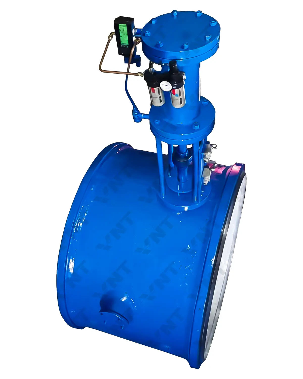
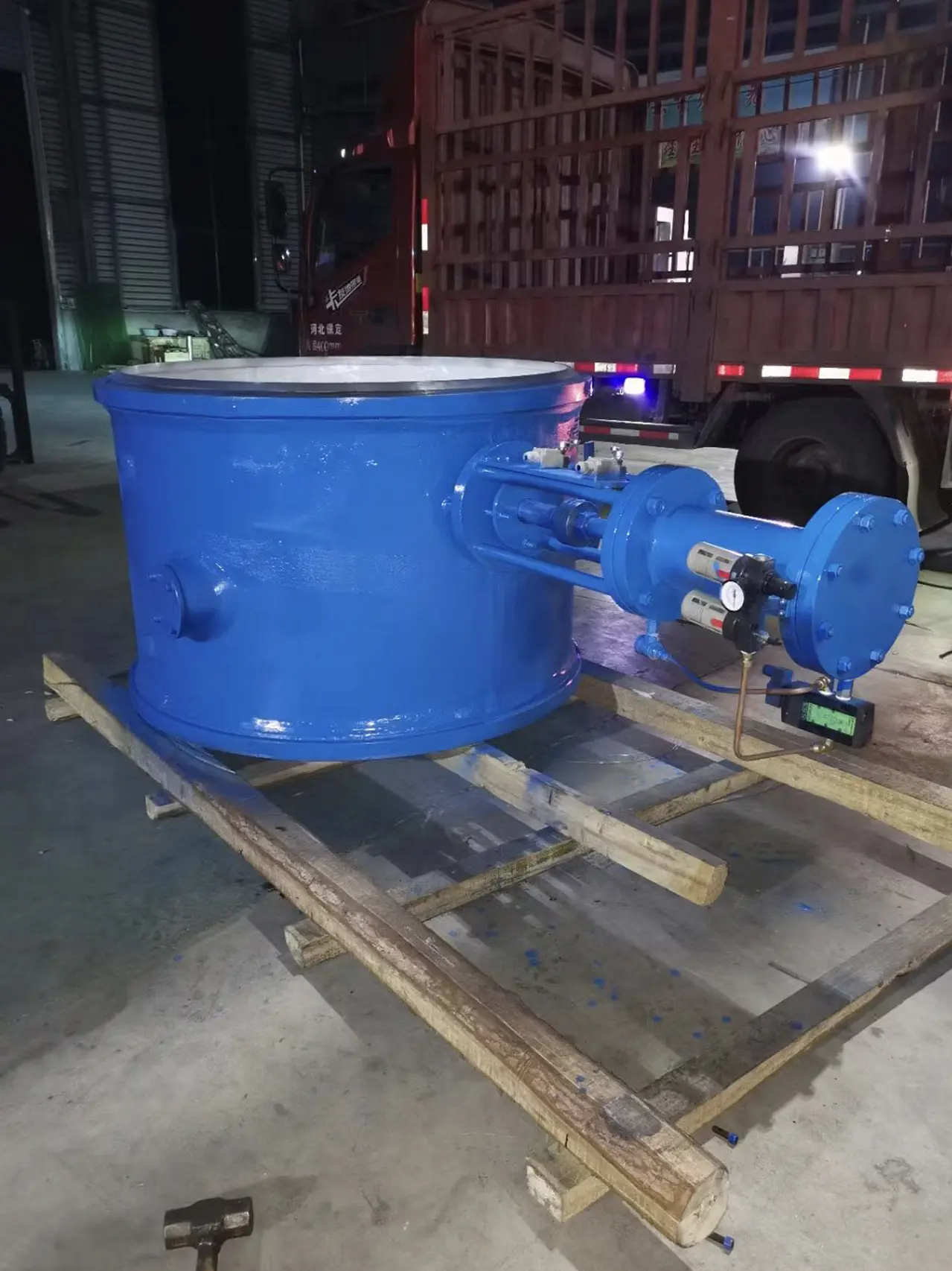
Tilting Disc Check Valve for Pump Discharge and Water Hammer Control
A self-actuated tilting disc check valve for pump discharge and water-transmission systems, with optional counterweight or hydraulic damping for engineered closing control.
| Size Range | NPS 2″–48″ (DN50–DN1200) |
|---|---|
| Pressure Rating | Class 150–900 (PN10–PN160) |
| Body Material | Carbon steel, alloy steel, stainless steel, duplex steel, etc. |
| End Connection | RF, BW |
| Operation | Self-actuated, optional counterweight or hydraulic damper |
Frequently Asked Questions
No. It uses a tilting disc mechanism with a different pivot geometry and closing response. The two designs should not be treated as interchangeable.
No. The valve can help control reverse velocity and closing response, but selection must be based on the piping system, pump trip conditions and transient or surge analysis.
The valve is self-actuated by flow and differential pressure. An optional counterweight or hydraulic damper can be engineered to modify the closing characteristic.
Installation orientation affects disc movement and closing behavior. Confirm the flow direction, shaft position and approved orientation on the certified drawing before installation.
Provide size, pressure rating, medium, temperature, pump curve, normal and maximum flow, line velocity, trip scenario, surge analysis, installation orientation, end connection and required closing time.
Product Overview
The tilting disc check valve is a self-actuated non-return valve for pump discharge, water transmission and other systems where reverse-flow response must be considered. Its off-centre pivot allows the disc to begin closing as forward velocity decreases, helping limit reverse velocity before full closure.
An optional counterweight or hydraulic damper can be engineered to adjust the closing characteristic. These devices do not replace system analysis: pump inertia, line profile, flow velocity, column separation and allowable surge pressure must be reviewed together.
Selection should confirm NPS or DN, pressure rating, body material, RF or BW ends, seat arrangement, operating temperature, installation orientation and available space for external accessories. The certified drawing should define flow direction, shaft position and maintenance clearances.
For pump protection and water-hammer control, provide the pump curve, normal and maximum flow, trip or power-failure scenario, reverse velocity, surge-analysis results and required closing curve. This allows the valve and optional damping equipment to be matched to the actual hydraulic duty.
- Tilting Disc Mechanism: responsive closing as forward velocity decays.
- Self-Actuated Operation: no external power required for normal check-valve action.
- Optional Closing Control: counterweight or hydraulic damper engineered for the project.
- Project-Based Selection: materials, ends and closing behavior matched to the system datasheet.
Related Check Valve Selection Guides
← Back to Check Valve ProductsDiscuss Your Tilting Disc Check Valve Requirements
Send the pump data, surge analysis and valve datasheet for engineering review and quotation.
Applications, Materials and Engineering Selection
Use the complete hydraulic duty—not pressure class alone—to confirm valve size, closing response, materials, end connection, orientation and optional closing-control equipment.
Typical Applications
- Pump discharge and booster-station piping
- Municipal and industrial water-transmission lines
- Cooling-water, utility-water and power-plant systems
Materials and End Connections
Carbon, alloy, stainless and duplex steel body materials are available. RF flanged or BW ends, seat materials, shaft components and bolting must match the pressure-temperature rating, water chemistry and project piping specification.
Technical Points to Verify
- Pump curve, line velocity and trip condition
- Reverse velocity, closing time and allowable surge
- Flow direction, shaft position and installation orientation
- Counterweight or hydraulic-damper settings when specified
Related resources: Water and Wastewater Applications · Check Valve Selection Guide · Contact Vornet
Procurement and Inspection Checklist
Select this valve from the complete pump and piping duty. The surge model, closing characteristic and installation arrangement should be reviewed together.
- Service data: state NPS or DN, class or PN, medium, design pressure, temperature, normal and maximum flow, pump curve and line velocity.
- Transient review: provide pump-trip scenarios, reverse velocity, allowable pressure rise, column-separation risk, surge-analysis results and the required closing curve.
- Installation: confirm flow direction, shaft position, approved orientation, straight-pipe conditions and clearance for any counterweight or hydraulic damper.
- Construction: confirm body and internal materials, RF or BW ends, seat arrangement, shaft or hinge components, bolting and coating requirements.
- Inspection: request material certificates, dimensional checks, shell and seat tests, free disc movement and functional checks of optional closing-control equipment.
Review the water and wastewater application guide, compare the check valve selection guide, or send the pump and surge data for engineering review.