3-Way Ball Valve L-Port vs T-Port: Complete Flow Pattern Selection Guide
Every engineer who has specified a 3-way ball valve for flow diversion or mixing has encountered the L-port versus T-port decision. The difference is a single internal passage configuration — but that choice determines whether the valve diverts, selects, mixes, or shuts off. Choosing wrong means either a pressure drop that starves a downstream process, or cross-contamination between streams that compromises product quality.
The distinction is entirely in the ball’s internal flow path. In an L-port ball valve, the ball has a single L-shaped passage that connects the common port to one of two outlet ports at a time. The port arrangement forms a 90-degree turn inside the ball, which creates a pressure drop but provides positive shutoff on one port while flow passes through the other.
In a T-port ball valve, the ball has a T-shaped passage that connects all three ports simultaneously when fully open, or can connect the common port to both outlets at once. The straight-through path in one position offers full-port flow equivalent to a 2-way ball valve, while the T-configuration allows mixing flow from two inlets into one outlet.
Here is why this matters in practice: an L-port valve specified for a manifold selector service where the operator needs to isolate a dead leg will work perfectly — the L-port blocks one port entirely. But that same L-port, if installed in a blending application where two parallel pumps need to feed into a common header, will create a 90-degree pressure drop that the pump may not have headroom to overcome. The T-port handles this with a straight-through path. Understanding this single geometric distinction is the foundation of every selection decision that follows.
2. L-Port Ball Valve — Diverter Configuration
Design and Operating Principle
An L-port 3-way ball valve features a ball with a single L-shaped bore. The ball rotates 90 degrees to shift flow from one port to another. At any position, the common port (usually the bottom port) is connected to one of the two outlet ports while the third port is positively isolated. The ball’s L-shaped passage creates a 90-degree flow path in both operating positions.
| Parameter | L-Port Specification |
|---|---|
| Flow Path | 90-degree turn at all open positions |
| Port Blocking | One port fully isolated at each position |
| Flow Coefficient (Cv) | 55-65% of equivalent 2-way ball valve |
| Number of Flow Positions | 2 |
| Mixing Capability | No — cannot connect two inlets to one outlet |
| Shutoff Position | Yes — all ports blocked at intermediate position |
Where L-Port Ball Valves Perform Best
Manifold selector service — Selecting between two parallel filters, heat exchangers, or pumps while isolating the offline unit for maintenance.
Tank switching — Diverting product flow from one storage tank to another without interrupting the pipeline. Common in oil terminals, chemical storage farms, and refinery intermediate tanks.
Instrument isolation — Switching calibration gas sources to analyzers or selecting between sample points in a process analyzer system.
CIP/SIP circuits — Clean-in-place and sterilize-in-place systems where cleaning solution must be directed to specific equipment trains.
Where L-Port Valves Hit Their Limits
Mixing and blending — The L-port cannot connect two inlet streams to a single outlet.
High-viscosity fluids — The 90-degree flow turn creates a pressure drop that thick fluids struggle to overcome.
Slurry service — The L-shaped passage has a dead zone at the corner where solids can accumulate.
3. T-Port Ball Valve — Mixing and Full-Port Configuration
Design and Operating Principle
A T-port 3-way ball valve features a ball with a T-shaped bore. In the full open position, the T port aligns to create a straight-through path between two opposite ports while simultaneously connecting the third port. This configuration enables three distinct operating modes: full-through flow (straight path, no turn), diverting flow (common to one outlet), and mixing flow (two inlets to one outlet).
| Parameter | T-Port Specification |
|---|---|
| Flow Path | Straight-through in one position, 90° turn in others |
| Port Blocking | No port isolated — all three connected |
| Flow Coefficient (Cv) | 80-95% of equivalent 2-way (straight-through) |
| Number of Flow Positions | 3 |
| Mixing Capability | Yes — two inlets to one outlet |
| Shutoff Position | No — all ports remain connected |
Three Operating Positions of a T-Port Valve
Position 1: Straight-Through (Flow Path A ↔ B) — The T bore aligns to create a straight-through passage between two opposite ports. Flow passes with minimal restriction.
Position 2: Right Divert (Common C ↔ Port A) — Flow enters the common port and exits through one side port.
Position 3: Left Divert (Common C ↔ Port B) — Flow diverts to the opposite side port for alternating flow direction.
Where T-Port Ball Valves Perform Best
Continuous mixing and blending — Combining two product streams into a single pipeline. Common in chemical blending, fuel blending, and polymerization processes.
Heat exchanger circuits — Switching flow between parallel heat exchanger tubes or bypassing a fouled exchanger.
Pump recirculation — Directing pump discharge to either the process line or back to the suction tank during startup.
4. Side-by-Side Comparison Matrix
| Factor | L-Port | T-Port |
|---|---|---|
| Flow Path | 90° turn in all positions | Straight-through position available |
| Cv Rating | 55-65% of 2-way | 80-95% of 2-way |
| Port Isolation | One port fully blocked | All ports connected |
| Mixing Capable | No | Yes |
| Diverter Capable | Yes — primary function | Yes — secondary function |
| Pressure Drop | Higher (permanent 90° turn) | Lower (straight-through option) |
| Slurry Suitability | Poor — solids accumulate | Better — straight path available |
| Cost Factor | 1.0x (baseline) | 1.2-1.5x |
5. Industry-by-Industry Selection Guide
| Industry | Application | Recommended | Reason |
|---|---|---|---|
| Oil & Gas | Well test manifold | L-Port | Positive isolation of unused wellhead |
| Oil & Gas | Pipeline pig launcher | L-Port | Isolation of launcher barrel |
| Refining | Catalyst regeneration switching | T-Port | Continuous flow with zero dead-leg |
| Chemical | Reactant blending circuit | T-Port | Mixing two feed streams |
| Power Generation | Cooling water filter switch | L-Port | Select between duty/standby filters |
| Water Treatment | Backwash filter sequence | L-Port | Isolate filter vessel during backwash |
| Pharmaceutical | CIP solution routing | L-Port | Dead-leg prevention |
| Food & Beverage | Product blending station | T-Port | Mix multiple ingredients |
| HVAC | Chiller bypass circuit | T-Port | Proportional flow control |
| Storage | Tank farm manifold | L-Port | Select tank, isolate others |
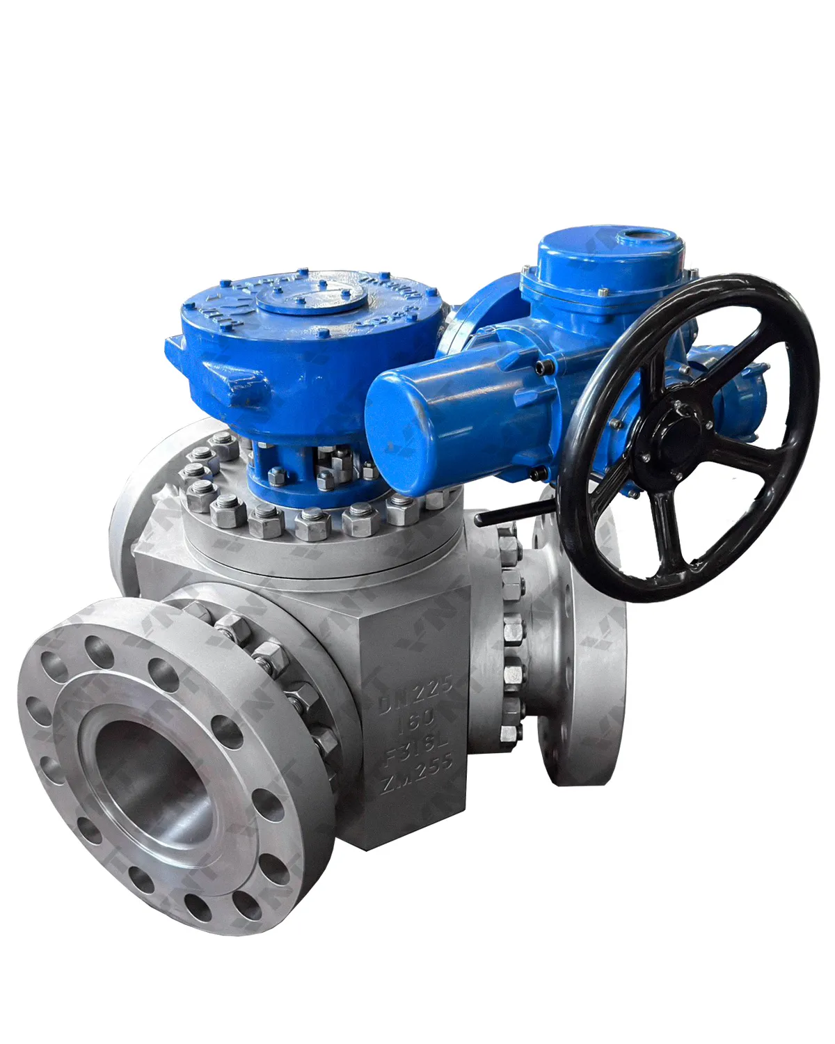
6. Actuation and Control Considerations
Both L-port and T-port valves can be operated with a standard 90-degree quarter-turn handle. For automated operation, pneumatic rack-and-pinion actuators or electric multi-turn actuators are available. The actuator must be sized for the highest seat load position — typically the closed port at full differential pressure for L-port, or all three ports simultaneously for T-port in mixing position.
For both L-port and T-port valves, a three-position limit switch box (or two individual switches with cam adjustment) is required to indicate which flow path is active. Standard two-switch boxes only indicate open/closed — for multi-port valves, specify a box with three adjustable cams.
7. Materials, Seats, and Pressure Ratings
Body Material Selection
| Material | Standard | Temp Range | Application |
|---|---|---|---|
| WCB (Carbon Steel) | ASTM A216 | -29°C to 425°C | General purpose |
| LCC (Low Temp) | ASTM A352 | -46°C to 345°C | Low-temp hydrocarbon |
| CF8M (316 SS) | ASTM A351 | -254°C to 815°C | Corrosive fluids |
| Duplex 2205 | ASTM A995 | -50°C to 300°C | Offshore, chloride service |
| Alloy 20 | ASTM A351 | -30°C to 400°C | Sulfuric acid service |
Seat Material Selection
| Seat Material | Max Temp | Leakage | Best For |
|---|---|---|---|
| PTFE (Virgin) | 180°C | Class VI | General service |
| RPTFE | 230°C | Class VI | Higher temperature |
| PEEK | 260°C | Class V-VI | High-temp, high-cycle |
| Metal (Stellite) | 680°C | Class IV-V | Fire-safe, abrasive |
Looking for industrial 3-way ball valves? Browse our complete ball valve range featuring L-port, T-port and custom configurations for your application.
8. Frequently Asked Questions
Q1: What is the main difference between an L-port and a T-port 3-way ball valve?
A: The ball bore geometry. L-port has a single L-shaped passage that connects the common port to one outlet at a time while blocking the third port. T-port has a T-shaped passage that can connect all three ports simultaneously. L-port is for diverter/selector service; T-port is for mixing service or full-through flow.
Q2: Can an L-port ball valve be used for mixing?
A: No. The L-port geometry only allows flow from the common port to one outlet at a time.
Q3: Can a T-port ball valve be used for diverting?
A: Yes, but the unused port is not fully isolated — it may see partial flow. If positive shutoff of the unused port is required, use an L-port instead.
Q4: Why does my L-port valve have higher pressure drop than expected?
A: L-port valves create a 90-degree flow turn in all positions, reducing Cv to 55-65% of an equivalent 2-way ball valve. Consider a T-port or increase valve size if low pressure drop is critical.
Q5: Which is better for slurry service?
A: T-port is generally better because it offers a straight-through position without corners where solids can accumulate.
Q6: Can 3-way ball valves be automated?
A: Yes. Both L-port and T-port valves can be fitted with pneumatic, electric, or hydraulic actuators sized for the highest seat load position.
Q7: What standards apply to 3-way ball valves?
A: API 6D (pipeline valves), ASME B16.34 (pressure-temperature rating), API 598 (pressure testing), API 607 (fire test), and ISO 17292 (metal ball valves).
Q8: What is the typical delivery time for 3-way ball valves?
A: Standard carbon steel L-port (NPS 1/2-6, Class 150-600): 2-4 weeks. Stainless steel T-port (NPS 2-8): 3-6 weeks. Exotic alloy (Class 900+): 8-14 weeks.